


PN25

BURKERT 355785 (Type 3320) electromotive 2/2-way angle seat shut-off valve with G 1/2 internal thread, DN15 orifice, 24 V DC drive, AG2 1300 N actuator, SAFEPOS energy-pack, and PN25 rating.
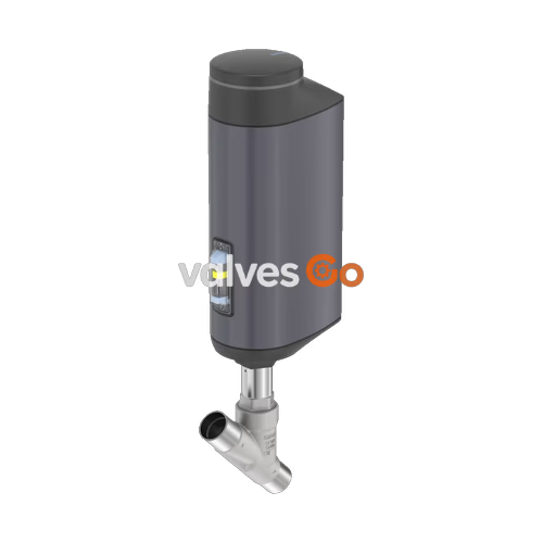
BURKERT 355785 (Type 3320) is an electromotive 2/2-way angle seat shut-off valve designed for demanding process automation environments. Driven by a brushless 24 V DC motor coupled to a precision ball screw linear mechanism, the size AG2 actuator generates a 1300 N linear driving force, displacing the valve swivel plate at speeds up to 6 mm/s. The unit features an internal G 1/2 threaded port (DIN ISO 228-1), a DN15 seat orifice, and a rated water flow coefficient (Kv) of 5.4 m³/h. Configured with a factory delivery status of normally closed (NC) through the integrated SAFEPOS energy-pack module, the valve reliably closes the flow path upon power loss without relying on external pneumatic pressure.
| Parameter | Value |
|---|---|
| Type | 3320 |
| Article Number | 355785 |
| Circuit Function | 2/2-way on/off shut-off valve |
| Port Connection | G 1/2 internal thread (DIN ISO 228-1) |
| Orifice / Nominal Seat Size | DN 15 (15 mm / 9/16") |
| Operating Pressure Range | 0 to 25 bar(g) |
| Nominal Pressure Rating | PN 25 (DIN EN 1333), Class 150 (DIN EN 1759) |
| Flow Direction | Below seat (against closing direction) |
| Flow Rate (Kv Water) | 5.4 m³/h (Cv 6.2 gpm) |
| Typical Closing Time | 2.2 s (2200 ms) |
| Travel Speed | 6 mm/s |
| Supply Voltage | 24 V DC ± 10 % (maximum residual ripple 10 %) |
| Operating Current | Max. 3 A (including 1 A charging current for SAFEPOS energy-pack; +2 A at min. temperature) |
| Standby Power Consumption | 2 to 4 W |
| Duty Cycle | 100 % continuous |
| Fail-Safe Safety Position | Normally closed (NC), via SAFEPOS energy-pack |
| Seat Seal Material | PTFE (Polytetrafluoroethylene) |
| Valve Body Material | Stainless steel CF3M |
| Actuator Size | AG2 (1300 N driving force) |
| Operating Medium Temperature | -10 °C to +130 °C |
| Permissible Ambient Temperature | -25 °C to +65 °C (without external modules) |
| Ingress Protection Rating | IP65 / IP67 (DIN EN 60529), NEMA 4X |
| Protection Class | III (DIN EN 61140) |
| Weight | Up to 5.5 kg (AG2 actuator assembly) |
The Type 3320 AG2 linear drive consists of a brushless DC motor, reduction gear, and threaded spindle mechanism that transfers force to the valve stem and closure plate. The system maintains tight shut-off even at the maximum operating pressure of 25 bar(g) in a de-energized holding state.
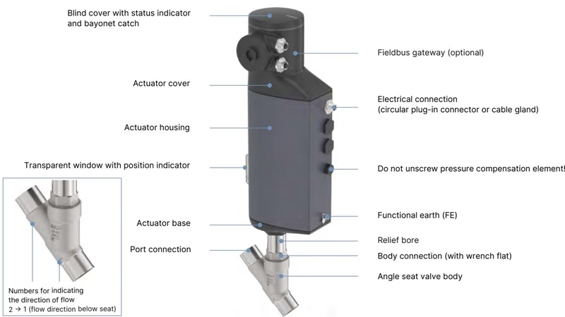
Wetted metal components are constructed from investment-cast stainless steel CF3M and precision wrought 316/316L alloys. The spindle packing utilizes self-adjusting PTFE V-rings preloaded with a spring assembly. All wetted materials meet European Regulation (EC) 1935/2004 requirements according to the manufacturer declaration.
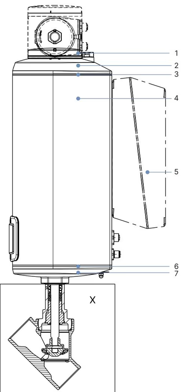
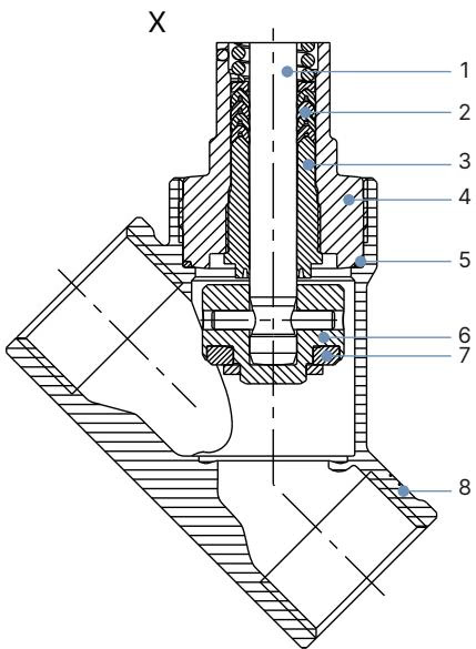
| Item No. | Component | Material |
|---|---|---|
| Actuator AG2 | ||
| 1 | Blind cover / gateway housing | PPS (standard), stainless steel 1.4301 (ATEX/IECEx) |
| 2 | Actuator cover | PPS |
| 3 | Static seal | EPDM |
| 4 | Actuator housing | Powder-coated aluminium |
| 6 | Seal | EPDM |
| 7 | Actuator base | PPS |
| Valve Body & Trim | ||
| 1 | Spindle (stem) | Stainless steel 1.4401 (316) / 1.4404 (316L) |
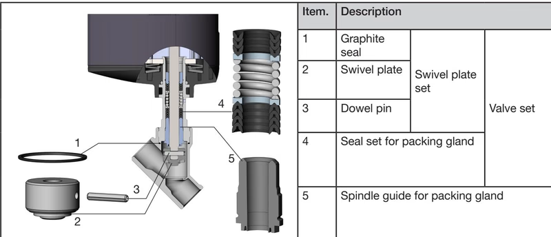
| 2 | Spindle packing seal | PTFE V-seals (filled) with spring compensation |
| 3 | Spindle guide bushing | PEEK or stainless steel 1.4404 (316L) |
| 4 | Packing gland tube | Stainless steel 1.4401 (316) |
| 5 | Body gasket | Graphite or PTFE |
| 6 | Swivel plate | Stainless steel 1.4401 (316) / 1.4404 (316L) |
| 7 | Valve seat seal washer | PTFE sealing washer |
| 8 | Valve body | Stainless steel CF3M |
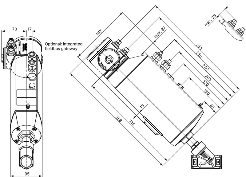
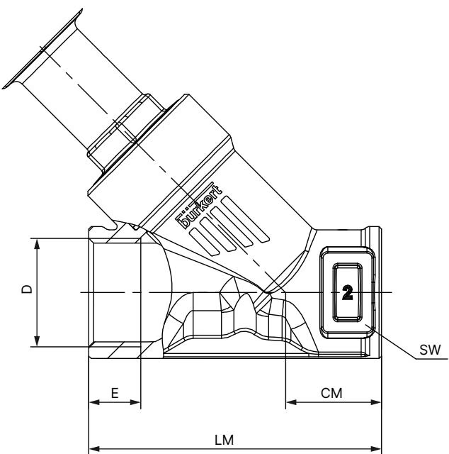
| Connection DN | Thread D | Thread Depth E [mm] | Body Center Height CM [mm] | Face-to-Face LM [mm] | Hex Wrench Flat SW [mm] | Total Height H1 (AG2 Standard) [mm] |
|---|---|---|---|---|---|---|
| DN 15 | G 1/2 | 14 | 24 | 65 | 27 | 311 |
| DN 20 | G 3/4 | 16 | 27 | 75 | 34 | 319 |
| DN 25 | G 1 | 18 | 29.5 | 90 | 41 | 321 |
| DN 32 | G 1 1/4 | 16 | 36 | 110 | 50 | 330 |
| DN 40 | G 1 1/2 | 18 | 35 | 120 | 55 | 333 |
| DN 50 | G 2 | 24 | 45 | 150 | 70 | 367 |
INFO
Height dimension H1 is given without sealing lift: the actuator rises by approximately 2 mm when seated in the closed position.
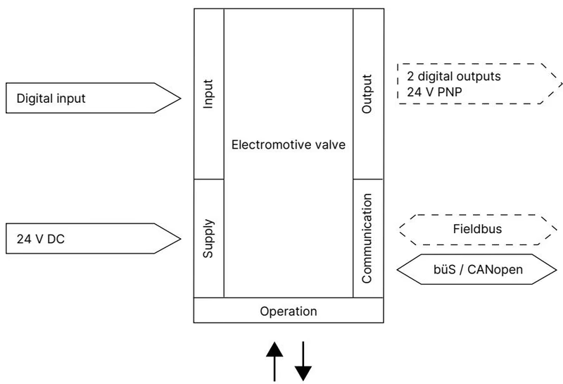
Article 355785 utilizes cable feed-through terminals for standard binary switching control. Actuation commands follow standard digital input levels (0 to 5 V = low / log "0"; 10 to 30 V = high / log "1"). Two digital outputs provide feedback signals with individual 100 mA current limits.
Pressure Hazard
Before performing any disassembly, relieve fluid pressure and vent or drain all connected pipelines. Never remove an actuator from a pressurized valve.
Valve Position during Removal
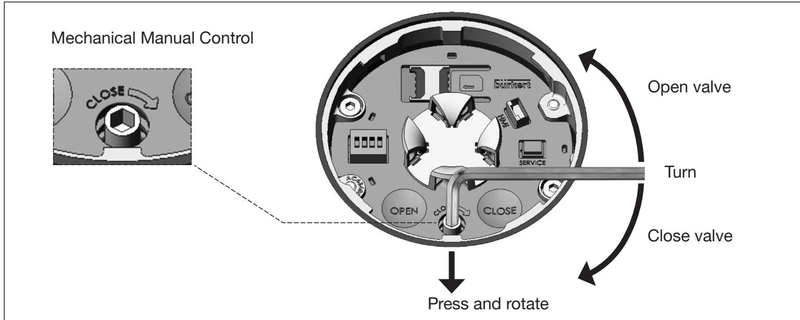
The valve must be driven to the fully open position before unscrewing the actuator from the valve body. Attempting to disassemble the unit while closed damages the seat seal and swivel plate.
| Connection Size DN | Tightening Torque [Nm] |
|---|---|
| DN 15 | 45 ± 3 |
| DN 20 | 50 ± 3 |
| DN 25 | 60 ± 3 |
| DN 32 | 65 ± 3 |
| DN 40 | 65 ± 3 |
| DN 50 | 70 ± 3 |
| DN 65 | 100 ± 3 |
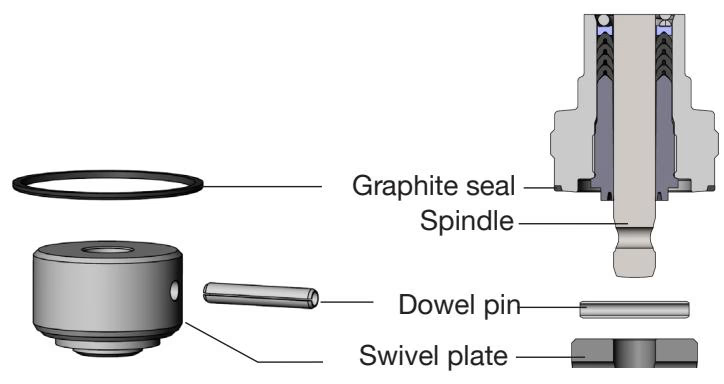
For DN15 (connection size 10/15) units, packing gland maintenance is performed by uncoupling the actuator base:
Electrical Discharge
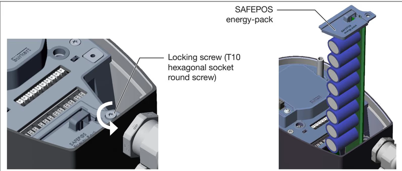
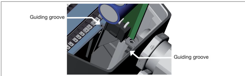
Switch off main power and allow the SAFEPOS energy storage pack to discharge completely before opening the housing. Wait until the LED light ring turns completely off.
Zero-Pressure Requirement
Never execute the X.TUNE function while the valve is under process pressure. An incorrect calibration under medium load will lead to improper seat seating and uncontrolled valve movement.
Under normal conditions, re-running X.TUNE is not required after factory shipment unless the valve body or seat has been altered. To execute manual calibration: ensure the line is depressurized, remove the dummy cover, and simultaneously depress the OPEN and CLOSE buttons for 5 seconds. Rapid LED flashing confirms calibration progress; steady illumination signals completion.
Explore similar products in our catalog



