

PN16

BURKERT 703301 Type 8640 modular pneumatic valve island features an 11-bank configuration, 19 mm station width, G 1/4 supply ports, bottom D6 working ports, and Sub-D 25-pin multi-pole control.
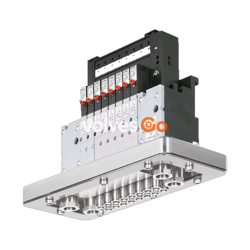
BURKERT 703301 (Type 8640) is a modular pneumatic valve island configured with 11 valve stations on a 19 mm grid width. Engineered for centralized pneumatic control in process automation, this assembly combines Type 5470 pneumatic directional valves with integrated Type 6106 pilot valves. The assembly provides G 1/4 supply ports, D6 push-in working connections positioned at the bottom of the block, and electrical actuation through a Sub-D 25-pin multi-pole interface. It operates within a nominal pressure range of 2.0 to 8.0 bar and delivers an IP54 degree of protection when installed with matching connectors.
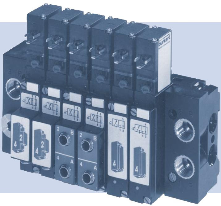
The Type 8640 pneumatic system integrates modular base rails (Type MP05) with Type 5470 directional control valves. Each valve station incorporates a Type 6106 3/2-way pilot valve mounted on a valve body containing seat seals, diaphragm elements, and internal switching pathways. Fluid supply and exhaust are routed through centralized manifold galleries, while working air is directed through dedicated service ports.
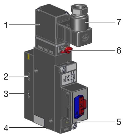
| Item | Designation | Function |
|---|---|---|
| 1 | Pilot valve Type 6106 | 3/2-way solenoid actuator controlling pilot stage |
| 2 | Exhaust port 3 | Common vent connection for de-actuation air |
| 3 | Pressure port 1 | Main pneumatic supply channel |
| 4 | Working port 4 | Pneumatic output channel A |
| 5 | Working port 2 | Pneumatic output channel B |
| 6 | Manual override | Mechanical testing switch |
| 7 | Cable plug Type 2506 / connector | Electrical command interface |
Pneumatic connections follow standardized numbering across the block:
Each valve station is equipped with a mechanical override switch to facilitate setup and functional testing without electrical power.
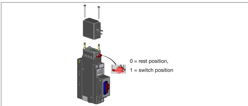
To actuate the valve manually, press the manual override pin and rotate it 90° clockwise until it hits the internal mechanical stop. The override locks in position and will not return automatically. To reset, turn the pin 90° counterclockwise back to its zero position.
Manual Override Safety
Operate the manual override only when the electrical power is disconnected. Ensure the manual override is completely returned to its neutral zero position before initiating normal electrical operation.
Type 5470 valves support multiple flow path configurations, including 3/2-way and 4/2-way operation:
A standard 4/2-way valve station can be reconfigured into a 3/2-way function by inserting a dedicated blind plug into one of the working outlets.
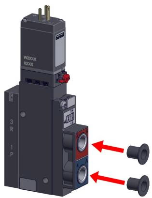
| Port 2 Status | Port 4 Status | Resulting Circuit Function |
|---|---|---|
| Closed (with stopper) | Open | Function C (Normally Closed) |
| Open | Closed (with stopper) | Function D (Normally Open) |
BURKERT 703301 complies with relevant EU harmonisation legislation and technical standards. Operating conditions must be maintained within the following parameters:
| Parameter | Specified Value |
|---|---|
| Nominal Operating Pressure Range | 2.0 bar to 8.0 bar |
| Pilot Pressure Range | 2.0 bar to 10.0 bar (must be at least 70% of operating pressure) |
| Required Pressure Differential | Minimum 2 bar difference between port 1 and port 3 |
| Medium Temperature | 0 °C to +50 °C (operation restricted to dried air below 0 °C) |
| Ambient Temperature | 0 °C to +55 °C |
| Storage Temperature | -40 °C to +55 °C |
| Operating Fluid | Filtered compressed air (particle size ≤ 10 µm), neutral gases (≤ 5 µm filtering) |
| Lubrication Condition | Unlubricated preferred; lubricated air permissible |
| Seal Material | NBR |
| Voltage Tolerance | ±10% |
| Degree of Protection | IP54 (with properly installed Sub-D connector) |
Continuous Operation Cycling
To preserve functional switching reliability during extended periods of continuous energization or standby downtime, actuate each valve station 1 to 2 times per day.
Electrostatic Discharge (ESD) Protection
The internal control modules contain electronic components sensitive to electrostatic discharge. Follow EN 61340-5-1 handling protocols. Never touch conductive pins or circuit traces while supply voltage is active.
The valve block assembly consists of a left supply module, intermediate multi-station base segments (2-fold and 3-fold), individual valve units, and a right terminating module.
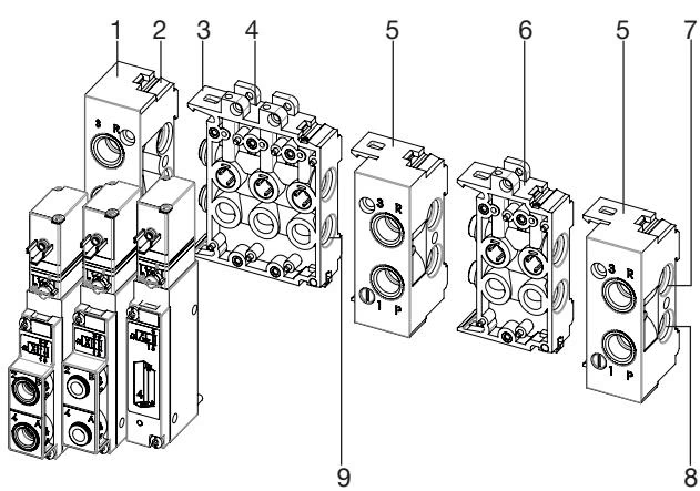
| Item | Component Description |
|---|---|
| 1 | Left connection module |
| 2 | Module latch tab |
| 3 | Module latch hook |
| 4 | Base module (3-fold) |
| 5 | Right connection module |
| 6 | Base module (2-fold) |
| 7 | Common exhaust channel 3 (R) |
| 8 | Common supply channel 1 (P) |
| 9 | Inter-module sealing O-rings |
Assembly procedure for modular blocks:
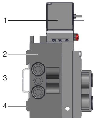
The complete 11-bank assembly can be mounted onto DIN rails or bolted directly to machine frames.
When individual Type 5470 valve units are decoupled or installed standalone, secure them via direct M4 fastening holes.
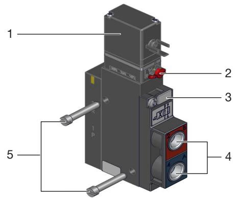
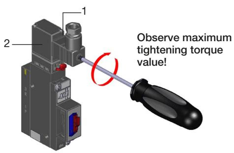
If installation constraints require cable entry from the opposite direction, the pilot valve coil can be rotated 180°:
Adhere strictly to the recommended torque limits when connecting rigid or threaded fittings into the aluminum and polymer ports:
| Port Size | Port Designation / Channel | Recommended Torque (Nm) | Maximum Torque (Nm) |
|---|---|---|---|
| G 1/4 or NPT 1/4 | Supply port 1 (P), Exhaust ports 3/5 (R/S) | 4 to 7 | 20 |
| G 1/8 or NPT 1/8 | Working ports 2/4 (A/B), Pilot feeds | 3 to 6 | 7 |
Working ports on Article 703301 are engineered as D6 push-in connectors positioned on the valve bottom. Main supply and exhaust ports utilize G 1/4 female threads.
Piping Preparation
Flush and purge all supply pipes prior to connection to remove manufacturing debris and metal shavings. Install an upstream dirt trap or filter regulator rated at ≤ 5 µm. Never use a solenoid coil as a lever arm when tightening threaded fittings.
Pneumatic hose lines must satisfy the following technical parameters:
| Material | Hose Outer Diameter (mm) | Permitted Deviation (mm) |
|---|---|---|
| Polyamide (PA) | 3 to 10 | ±0.08 |
| Polyamide (PA) | 12 to 16 | ±0.10 |
| Polyurethane (PU) | 3 to 8 | ±0.10 |
| Polyurethane (PU) | 10 to 16 | ±0.15 |
Push-in connections must withstand the standardized tensile proof forces listed below without disengaging or venting leaks:
| Hose OD (Metric) | Hose OD (Inch) | PA Hose Min. Tensile Force (N) | PU Hose Min. Tensile Force (N) |
|---|---|---|---|
| 3 mm | 1/8" (3.17 mm) | 60 | 25 |
| 4 mm | 5/32" (4.00 mm) | 70 | 50 |
| 6 mm | 1/4" (6.35 mm) | 120 | 100 |
| 8 mm | 5/16" (8.00 mm) | 170 | 150 |
| 10 mm | 3/8" (9.52 mm) | 250 | 200 |
| 12 mm | 1/2" (12.70 mm) | 300 | 200 |
| 14 mm | — | 300 | 250 |
| 16 mm | 5/8" (16.00 mm) | 350 | 300 |
Flexible Hose Retention
When using softer polyurethane (PU) tubing subject to mechanical movement or vibration, install internal support sleeves (Ident 20099400) inside the hose end to maximize retention and prevent seal distortion.
Article 703301 utilizes a centralized multi-pole Sub-D 25-pin connection. Individual valve plug connections follow DIN EN 175301-803 Form C specifications (such as Type 2516).
For bistable or pulse-driven pilot coils, adhere to the polarity switching logic below. Pulse duration must be at least 50 ms.
| Electrical Pin Configuration | Pilot Stage State | Resulting Port Pathway (Function G) | Resulting Port Pathway (Function C) |
|---|---|---|---|
| (+) on pin 2 / (-) on pin 1 | Pilot valve energized open | 1 to 3, 2 to 3 | 1 to 4 |
| (+) on pin 1 / (-) on pin 2 | Pilot valve de-energized closed | 1 to 2, 4 to 3 | 4 to 3 |
| Fault Symptom | Probable Root Cause | Corrective Action |
|---|---|---|
| Valves fail to switch | No supply voltage or operating voltage below tolerance | Verify power circuit wiring and ensure voltage matches nameplate ratings (24 V DC ±10%). |
| Manual override locked in non-zero position | Reset manual override detent back to neutral zero position. | |
| Supply pressure insufficient (< 2 bar) | Establish pressure supply above 2.0 bar minimum threshold. Verify supply lines and upstream regulators. | |
| Valves switch sluggishly or vent continuously through exhaust | Operating pressure supply volume inadequate | Ensure volume capacity is sufficient across all upstream filters, regulators, and shut-off valves. |
| System pressurized while valves were in energized position | Ensure pilot valves are de-energized (home position) during initial pneumatic pressurization. | |
| Exhaust backpressure due to clogged or undersized silencers | Clean contaminated silencer inserts or install larger exhaust mufflers / expansion vessels. | |
| Contamination or particulates inside pilot valve mechanism | Apply rapid pressure pulses through exhaust galleries to clear debris, or replace the pilot valve capsule. | |
| External leakage between manifold modules | Missing, pinched, or damaged inter-module O-rings | Disassemble module junction, inspect seal seats, and replace damaged O-rings. |
| Displaced flat gasket between valve body and sub-base | Re-seat the interface gasket or replace with a new seal, tightening valve screws to 0.6 ±0.1 Nm. |
Explore similar products in our catalog


