98% Separation Efficiency

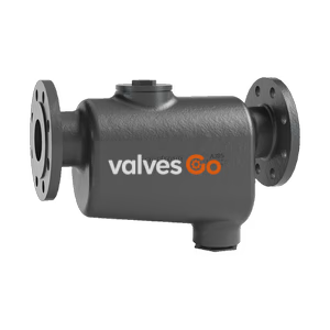
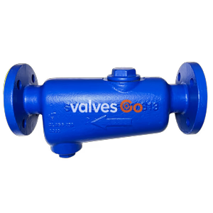
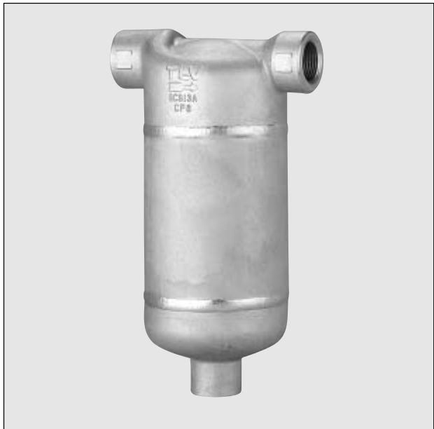
TLV DC7 high efficiency stainless steel cyclone separator. All-welded, maintenance-free construction for steam and air, achieving up to 98% condensate separation.
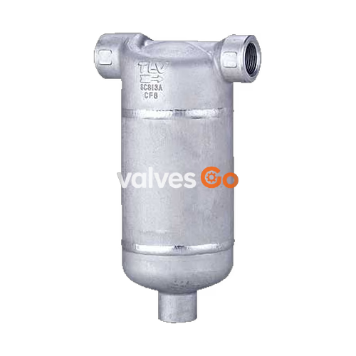
TLV DC7 is a welded-unit construction cyclone separator that uses centrifugal force to separate condensate from steam or air in piping lines. This cyclone separator is suitable for use in process applications that require high-quality steam or air up to 2.5 MPaG (355 psig).
WARNING
Do not use for toxic, flammable or otherwise hazardous fluids. This product is a separator for steam or air that separates condensate from steam or air piping systems. Use only for steam, air and/or condensate.
All stainless steel separator, employing a cyclone-effect to efficiently separate condensate from steam and air.
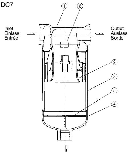
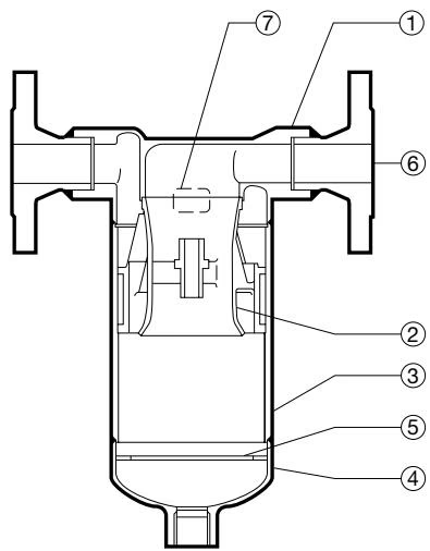
| No. | Description | No. | Description |
|---|---|---|---|
| 1 | Body | 4 | Separator Bottom |
| 2 | Separator | 5 | Baffle |
| 3 | Separator Body | 6 | Nameplate |
| Model | DC7 |
|---|---|
| Connection | Screwed, Socket Welded, Flanged |
| Size | 1/2", 3/4", 1", 1 1/2", 2" / DN 15, 20, 25, 40, 50 |
| Maximum Operating Pressure (barg) PMO | 25 |
| Maximum Operating Temperature (°C) TMO | 300 |
| Applicable Fluids* | Steam, Air |
Materials
| No. | Description | Material | DIN* | ASTM/AISI* |
|---|---|---|---|---|
| 1 | Body | Cast Stainless Steel A351 Gr.CF8 | 1.4312 | - |
| 2 | Separator | Cast Stainless Steel SCS13 | 1.4308 | A351 Gr.CF8 |
| 3 | Separator Body | Stainless Steel SUS304 | 1.4301 | AISI304 |
| 4 | Separator Bottom | Cast Stainless Steel A351 Gr.CF8 | 1.4312 | - |
| 5 | Baffle | Stainless Steel SUS304 | 1.4301 | AISI304 |
| 6 | Flange** | Stainless Steel SUS304/Cast Stainless Steel A351 Gr.CF8 | 1.4301/1.4312 | AISI304/ |
| 7 | Nameplate | Stainless Steel SUS304 | 1.4301 | AISI304 |
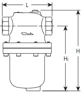
| Size* | DN** | L (mm) | H (mm) | H1 (mm) | φW (mm) | φD (mm) | φC (mm) | Weight(kg) |
|---|---|---|---|---|---|---|---|---|
| 1/2" | 15 | 130 | 229 | 210 | 89 | 36 | 21.8 | 3.4 |
| 3/4" | 20 | 130 | 229 | 210 | 89 | 36 | 27.2 | 3.4 |
| 1" | 25 | 150 | 263 | 240 | 101 | 44 | 33.9 | 5.3 |
| 1 1/2" | 40 | 170 | 326 | 295 | 114 | 59 | 48.8 | 6.5 |
| 2" | 50 | 220 | 397 | 360 | 165 | 72 | 61.2 | 15 |
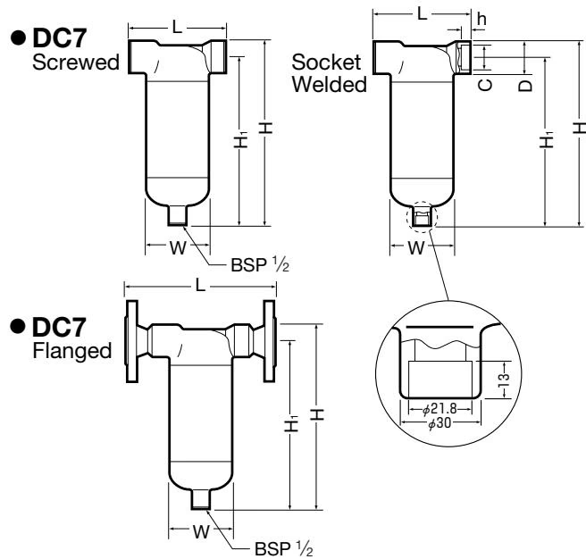
| DN | L (DIN 2501 PN25/40) | L (ASME Class 150RF) | L (ASME Class 300RF) | H (mm) | H1 (mm) | φW (mm) | Weight*(kg) |
|---|---|---|---|---|---|---|---|
| 15 | 198 | 178 | 178 | 229 | 210 | 89 | 5.0 |
| 20 | 202 | 191 | 191 | 229 | 210 | 89 | 5.6 |
| 25 | 232 | 227 | 227 | 263 | 240 | 101 | 8.1 |
| 40 | 252 | 251 | 258 | 326 | 295 | 114 | 11 |
| 50 | 310 | 331 | 337 | 397 | 360 | 165 | 22 |
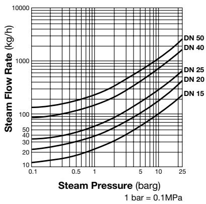
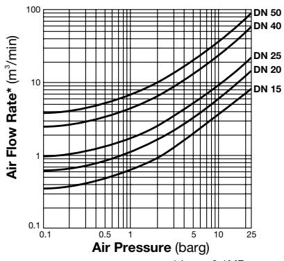
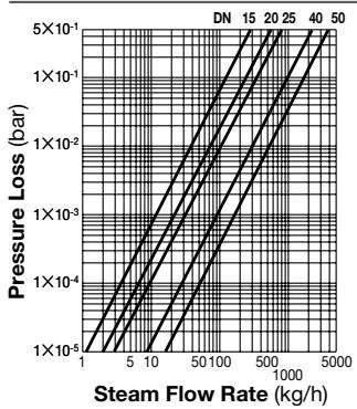
The pressure loss chart is based on a steam pressure of 10 barg. For other pressures, multiply the steam flow rate by the correction factor given in the table below. Use this value on the pressure loss chart.
| Pressure (barg) | 1 | 3 | 5 | 7 | 10 | 16 | 20 | 25 |
|---|---|---|---|---|---|---|---|---|
| Flow Rate Correction Factor | 2.24 | 1.62 | 1.34 | 1.16 | 1 | 0.81 | 0.73 | 0.67 |
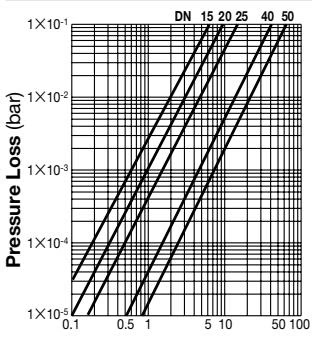
The pressure loss chart is based on an air pressure of 10 barg. For other pressures, multiply the air flow rate by the correction factor given in the table below. Use this value on the pressure loss chart.
| Pressure (barg) | 1 | 3 | 5 | 7 | 10 | 16 | 20 | 25 |
|---|---|---|---|---|---|---|---|---|
| Flow Rate Correction Factor | 5.5 | 2.75 | 1.83 | 1.38 | 1 | 0.65 | 0.52 | 0.44 |
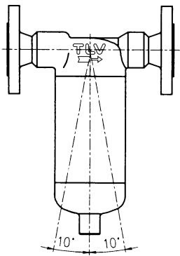
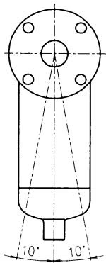
Allowable Inclination
If the expected performance is unachievable after installation of the separator, read the Proper Installation section again and check the following points to take appropriate corrective measures.
| Problem | Cause | Remedy |
|---|---|---|
| Condensate is mixed in with the steam or air from the separator outlet | Flow velocity is too high | Compare the specifications and actual operating conditions, and take steps necessary to lower the flow velocity |
| Condensate is mixed in with the steam or air from the separator outlet | Improper installation | Correct the installation |
Explore similar products in our catalog