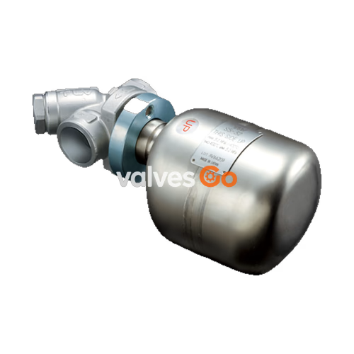
The TLV FS5 and FS5H QuickTrap® series are universal free float steam traps featuring thermostatic air venting and a two-bolt inline replaceable design. Constructed from stainless steel, these traps can be installed in any inclination, making them suitable for small and medium capacity applications between 0.01 and 4.6 MPaG (1 and 650 psig), such as saturated and superheated steam mains, branches, tracer lines, and small-to-medium process equipment.
The QuickTrap® design utilizes a precision-ground float, constant water seal, and a three-point seating mechanism to ensure a steam-tight seal, even under no-load conditions. The thermostatic air vent employs a bimetal strip for fast start-up, while the two-bolt flange connector allows the trap unit to be replaced in minutes without disturbing the pipeline.
Features
Inline replaceable 2-bolt universal flange steam trap for steam mains, tracers and light processes.
- Two-bolt flange connector permits trap replacement in minutes without disturbing piping.
- Universal flange allows trap to be positioned in the correct attitude, regardless of pipeline configuration.
- Precision-ground float, constant water seal and three-point seating design ensure a steam tight seal, even under no-load conditions.
- Thermostatic air venting with bimetal strip allows for fast start-up.
- One screen located in connector and one in trap ensure trouble-free operation.
Configuration
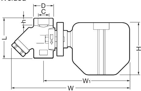
 Socket Welded
 Flanged
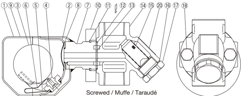
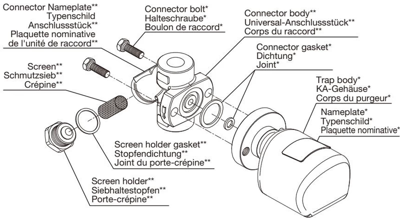
Exploded View
WARNING
Do not remove snap ring used to fix the connector flange.
Tightening Torque and Distance Across Flats:
| No. | Description | Tightening Torque N·m (lbf·ft) | Distance across flats mm (in) |
|---|
| 18 | Connector Bolt | 39 (28) | 14 (9/16) |
| 17 | Screen Holder F46 (All connections and sizes) | 100 (73) | 30 (1 3/16) |
| 17 | Screen Holder F32 (F: 15-25mm; S & W: 15, 20mm) | 60 (44) | 22 (7/8) |
| 17 | Screen Holder F32 (S & W: 25 mm) | 150 (110) | 38 (1 1/2) |
Proper Installation
- Before installation, be sure to remove all protective seals.
- Before installing the steam trap, blow out the inlet piping to remove all dirt and oil.
- In some instances, the trap unit and the connector body are sent as separate units. When attaching them together, make sure the connector gaskets are still in place after having removed their protective seal.
- There are no restrictions on the installation direction beyond the following conditions: a) The arrow on the connector body must point in the direction of condensate flow. b) The connector body must be adjusted so that the connector flange face (for connecting to the trap unit) is in the vertical plane. c) The nameplate on the trap unit must face upward. d) The trap unit must be inclined no more than 5° horizontally and front-to-back.
- Install a bypass valve to discharge condensate, and inlet and outlet valves to isolate the trap in the event of trap failure or when performing maintenance.
- Install the trap in the lowest part of the pipeline or equipment so the condensate flows naturally into the trap by gravity. The inlet pipe should be as short and have as few bends as possible.
- Install a check valve at the trap outlet whenever the condensate discharge pipe leads to a tank or recovery line, or whenever the condensate collection pipeline is connected to more than one trap.
- Support the pipes within 0.8 meters (2.5 ft.) on either side of the trap.
- In order to avoid excessive back pressure, make sure the discharge pipes are large enough.
- The use of unions is recommended to facilitate connection and disconnection of screwed models.
Allowable Inclination
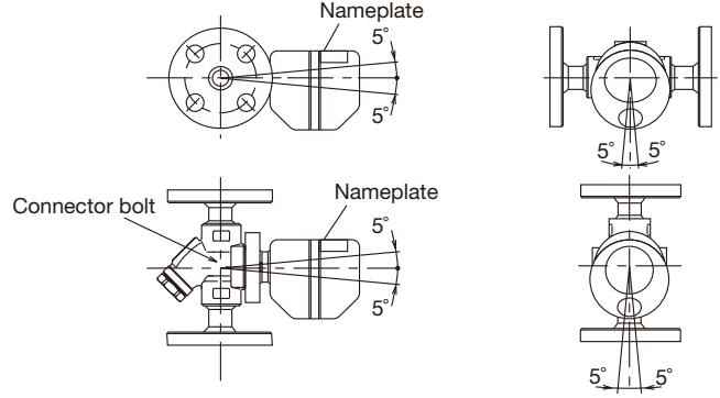
Installation Examples
Horizontal Piping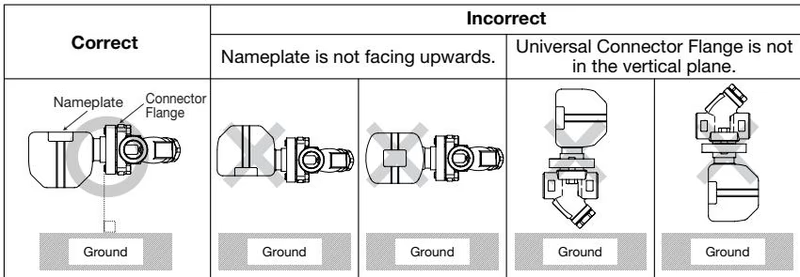
Vertical Piping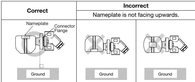
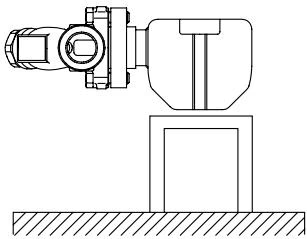
FS5/FS5H, Screwed Model Support
When using the product on a horizontal pipe, fasten it so that the trap cannot rotate. To ensure the correct operation of the FS5/FS5H Free Float Steam Trap, it is essential that the float mechanism is operating in the horizontal plane. When the screwed model is used in a horizontal pipe, there is a danger that the weight of the steam trap will cause the body to rotate on the pipe, so that the trap mechanism will no longer be in a horizontal plane. In order to prevent this from happening, it is important that the trap body be supported as shown.
Inspection and Maintenance
Operational inspections should be performed at least twice per year, or as called for by trap operating conditions.
Separating/Attaching Trap and Connector Bodies
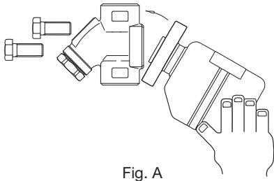
- Loosen and remove the connector bolts, remove the entire trap unit from the connector body and take it to a repair area where it can be supported in a vise during disassembly.
- When reinstalling the original trap: a. Using a small screwdriver, remove the old gaskets from their housings in the trap body, then clean the housings. b. New connector gaskets must be installed. c. To facilitate assembly and prevent loosening of the gaskets, apply a small amount of suitable adhesive at 120° intervals around the outer edge of the gaskets. d. Holding the trap body so that the gasket housings are horizontal, place the gaskets into the housings. When installing a replacement trap: a. Be sure to remove all protective seals, making sure the connector gaskets are still in place after having removed their seal. b. Before installation, scrape the mounting surface of the connector body clean using a soft tool.
- Align the bottom edge of the trap body with that of the connector body, making sure the gasket housings on the trap body align with the corresponding recesses in the connector body. Maintaining the proper alignment, close the tops together until the two faces are flush, making sure that connector gaskets remain in position.
- Insert the connector bolts and finger-tighten, keeping trap and connector bodies flush. Tighten the connector bolts to the proper torque.
Trap units S3/S5/S5H are designed for use with TLV F46 and F32 connector units, trap stations (V1/V2/V1PV2P Series) and QuickStation QS10/QS18. The connector unit name is indicated on the connector body.
Instructions for Disassembly and Reassembly of Plug/Holder
The seal on the threaded plugs/holders found on TLV products is formed by a flat metal gasket. The gasket may be pinched in the thread recesses during assembly if not installed carefully.
- Remove the plug/holder using a tool of the specified size.
- The gasket should not be reused. Replace it with a new gasket.
- Clean the gasket surfaces of the plug/holder and the product body.
- Coat both the gasket surface of the plug/holder and the threads with anti-seize, then press the gasket onto the center of the gasket surface of the plug/holder.
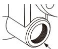

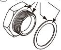

- Hold the plug/holder upside down to make sure that the anti-seize makes the gasket stick to the plug/holder.


- Screw the plug/holder by hand into the product body while making sure that the gasket remains tightly affixed to the center of the gasket surface.

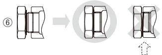
- Tighten the plug/holder to the proper torque.
- Begin the supply of steam and check to make sure there is no leakage.
Troubleshooting
| Problem | Cause | Corrective Measures |
|---|
| No condensate is discharged (blocked), or discharge is poor | Pressure exceeds maximum operating pressure | Replace trap with appropriately rated model or, if possible, reduce steam pressure |
| Pipelines upstream or downstream of the trap are clogged | Clean the pipelines |
| In the connector body, the screen or the inlet and outlet channels are clogged | Clean screen or channels |
| In the trap body, the inlet and outlet channels are clogged | Replace the trap body with a new one |
| The trap capacity is too small | Replace with larger trap |
| Steam locking has occurred | Perform a bypass blowdown, or close the trap inlet valve and allow the trap to cool |
| Steam leakage or blow-off | Trap is installed above the maximum allowable inclination | Correct the installation |
| Severe vibration of trap | Reinforce trap piping supports |
| Water hammer has occurred | Examine the piping for problems |
| Steam leaks from a place other than the outlet | Screen holder gasket or connector gaskets are loose or damaged | Tighten to the proper torque or replace gaskets |
Optional Blowdown Valve BD2
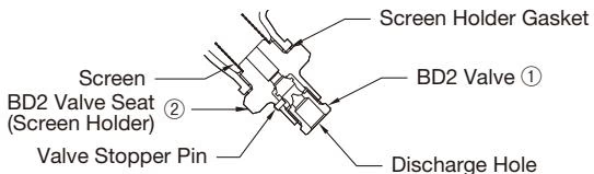
The BD2 Blowdown Valve, installed in place of the screen holder, uses internal pressure to blow out condensate/steam, dirt and scale to the atmosphere.

Reassembly of Blowdown Valve
- Clean the trap, BD2 threads, and sealing surfaces, and apply a small amount of anti-seize.
- Replace gasket.
- Carefully place the gasket over the threaded portion, and position carefully so that it does not become off-center.
- Fasten to the steam trap with the proper torque.
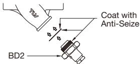
Torque (T) and Distance Across Flats (D)
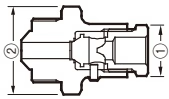
| Component | Connector Unit | Size | Specifications |
|---|
| ① | BD2 Valve | | | (T): 30 N·m (22 lbf·ft)
(D): 17 mm (21/32") |
| ② | BD2 Valve Seat (Screen Holder) | F46 | All connections and sizes | (T): 100 N·m (73 lbf·ft)
(D): 30 mm (1 3/16") |
| ② | BD2 Valve Seat (Screen Holder) | F32 | Flanged 15 - 25 mm
Screwed & Socket Welded 15, 20 mm | (T): 60 N·m (44 lbf·ft)
(D): 22 mm (7/8") |
| ② | BD2 Valve Seat (Screen Holder) | F32 | Screwed & Socket Welded 25 mm | (T): 150 N·m (110 lbf·ft)
(D): 38 mm (1 1/2") |
Operation Instructions for BD2
WARNING
Do not leave the vicinity while the blowdown valve is in the open position. Always wear eye protection and heat-resistant gloves.
- With two wrenches, firmly hold the BD2 Valve Seat (Screen Holder) ② in place while slowly opening the BD2 Valve ①. Be careful to avoid contact with fluid that will be discharged.
- Close the BD2 Valve ① and tighten to a torque of 30 N·m (22 lbf·ft), and confirm that there is no leakage.
Dimensions
Socket Welded