


PN16

TLV JL9X and JLH9X high-capacity process float steam traps with thermostatic air venting. Cast iron or cast steel body, up to 3.2 MPaG, inline repairable.
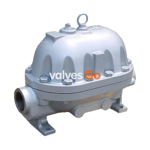
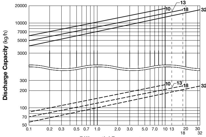
TLV JL9X and JLH9X inline repairable process float steam traps with thermostatic air vent (X-element) are suitable for large-capacity applications with operating pressures up to 3.2 MPaG (450 psig), such as large process and heating equipment. These traps discharge condensate continuously and automatically at a temperature slightly lower than saturation temperature.
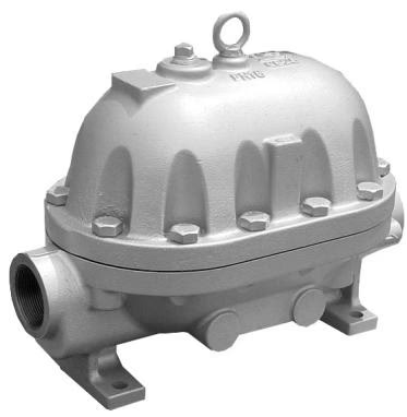
| Model | JL9X | JLH9X |
|---|---|---|
| Body Material | Cast Iron FC250 | Cast Steel A216/A216M Gr.WCB |
| Connection | Screwed, Flanged | Screwed, Socket Welded, Flanged |
| Size | DN 50 (2") | DN 50 (2") |
| Maximum Operating Pressure (PMO) | 1.0, 1.3 MPaG (10, 13 barg) | 1.0, 1.8, 3.2 MPaG (10, 18, 32 barg) |
| Maximum Operating Temperature (TMO) | 200 °C | 240 °C |
Pressure Shell Design Conditions
Maximum allowable pressure (PMA): 1.3 MPaG (JL9X), 3.2 MPaG (JLH9X). Maximum allowable temperature (TMA): 200°C (JL9X), 400°C (JLH9X). These are NOT operating conditions. Do not use this product outside the specification range.
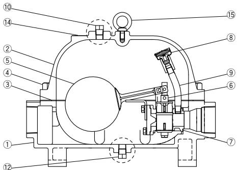
Cover plug and drain plug configuration for JLH9X differs slightly from JL9X.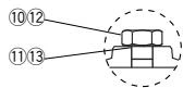
| No. | Description | Material |
|---|---|---|
| 1 | Body | Cast Iron (JL9X) / Cast Steel (JLH9X) |
| 2 | Cover | Cast Iron (JL9X) / Cast Steel (JLH9X) |
| 3 | Cover Gasket | Graphite/Stainless Steel |
| 5 | Float / Lever | Stainless Steel |
| 6 | Trap Unit (Main Valve Unit) | Cast Stainless Steel |
Piping Guidelines
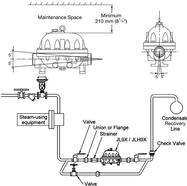
Note: If the trap inlet pressure exceeds 0.7 MPaG (100 psig), in order to ensure that an increase in back pressure does not prevent the rated flow capacity from being achieved, increase the size of the piping immediately after the trap to 80 mm (6”).
DANGER
NEVER apply direct heat to the float. The float may explode due to increased internal pressure, causing accidents leading to serious injury or property and equipment damage.




