


PN16

TLV SJ3FNX and SJ3FVX inline repairable free float steam traps with thermostatic air vent (X-element) for heat exchangers and process equipment up to 22 barg.
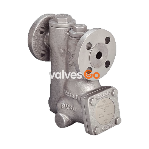
TLV SJ3FNX and SJ3FVX are inline repairable free float steam traps with a thermostatic air vent (X-element). They are suitable for a wide range of applications with small-to-large capacities and pressures up to 22 barg, such as heat exchangers, tank heaters, dryers, and process equipment. The traps discharge condensate continuously and automatically, at a temperature slightly lower than saturation temperature.
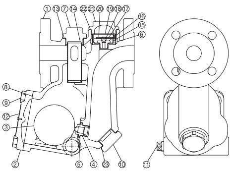
| No. | Description | No. | Description |
|---|---|---|---|
| 1 | Body | 12 | Screen Holder Gasket |
| 2 | Cover | 13 | Air Vent Screen |
| 3 | Float | 14 | Element Cover Gasket |
| 4 | Orifice | 15 | X-element Guide |
| 5 | Orifice Gasket | 16 | Air Vent Valve Seat |
| 6 | Screen | 17 | Air Vent (X-element) |
| 7 | Screen Holder | 18 | Snap Ring |
| 8 | Cover Gasket | 19 | Air Vent Valve |
| 9 | Cover Bolt | 20 | Spring Clip |
| 10 | Drain Plug / Orifice Plug | 21 | Element Cover |
| 11 | Plug |
Note: Replacement float available. Only parts for SJ3FNX/SJ3FVX are shown.
WARNING
Maximum allowable pressure (PMA) and maximum allowable temperature (TMA) are PRESSURE SHELL DESIGN CONDITIONS, NOT OPERATING CONDITIONS.
To avoid malfunctions, product damage, accidents or serious injury, install properly and DO NOT use this product outside the specification range.
DANGER
NEVER apply direct heat to the float. The float may explode due to increased internal pressure, causing accidents leading to serious injury or damage to property and equipment.
Horizontal Model (SJ3FNX)
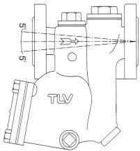
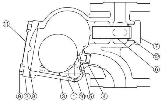
Vertical Model (SJ3FVX)
| Requirement | Correct | Incorrect |
|---|---|---|
| Install a catchpot with the proper diameter. | Diameter is too small. | |
| Make sure the flow of condensate is not obstructed. | Diameter is too small and inlet protrudes into pipe. | |
| To prevent rust and scale from flowing into the trap, connect the inlet pipe 25 - 50 mm (1 - 2 in) above the base of the T-pipe. | Rust and scale flow into the trap with the condensate. | |
| When installing on the blind end, make sure nothing obstructs the flow of condensate. | Condensate collects in the pipe. |
Operational inspections should be performed at least twice per year, or as called for by trap operating conditions. Steam trap failure may result in temperature drop in the equipment, poor product quality or losses due to steam leakage.
Parts Inspection Procedure
| Part | Inspection Item |
|---|---|
| Body, Cover | Check inside for damage, dirt, grease, oil film, rust or scale |
| Gaskets | Check for warping or damage |
| X-element | Check for damage |
| Screen | Check for clogging, corrosion or damage |
| Float | Check for deformation, damage, oil film or water inside |
| Air Vent Valve Seat, Orifice | Check for rust, scale, oil film, wear or damage |
A visual inspection can be carried out to aid in determining the necessity for immediate maintenance or repair, if the trap is open to atmosphere. If the trap does not discharge to atmosphere, use diagnostic equipment.
| Problem | Cause | Remedy |
|---|---|---|
| No condensate is discharged or discharge is poor | Float is damaged or filled with condensate | Replace the float |
| Orifice, screen or piping is clogged with rust or scale | Clean | |
| Steam-locking has occurred | Blowdown through the bypass or close the trap inlet valve and allow the trap to cool | |
| X-element is damaged | Replace the X-element | |
| Trap operating pressure exceeds maximum specified | Compare specifications and actual conditions | |
| Steam is discharged or leaks from trap outlet | Rust and scale accumulated around orifice or under float | Clean |
| Orifice is damaged | Replace the orifice | |
| Float is deformed or coated with scale | Clean or replace the float | |
| Trap is installed above maximum allowable inclination | Correct the installation | |
| Vibration of trap occurs | Lengthen inlet piping, fasten securely | |
| X-element is damaged or clogged | Clean or replace the X-element |




