Cast Iron

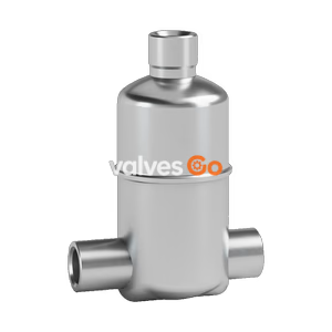
The TLV SS1VG-R is a stainless steel free float drain trap designed for air and inert gas systems. Features tight shut-off with a rubber orifice and three-point seating, operating up to 10 barg.
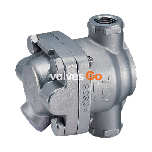
The TLV SS1VG-R is a stainless steel free float drain trap designed for air and inert gas systems. Featuring a rubber orifice and three-point seating, it provides a tight seal even under no-load conditions. The self-modulating free float ensures continuous, smooth, and low-velocity condensate discharge as process loads vary. A related model, the SS1VG-M, features a metal orifice for higher pressure and temperature applications.
WARNING
DO NOT use for toxic, flammable or otherwise hazardous fluids. This product is a drain trap that discharges condensate from air or inert gas systems. Use only for air or inert gas.
DANGER
NEVER apply direct heat to the float. The float may explode due to increased internal pressure, causing accidents leading to serious injury or damage to property and equipment.
WARNING
Install properly and DO NOT use this product outside the recommended operating pressure, temperature and other specification ranges. DO NOT use this product in excess of the maximum operating pressure differential; such use could make discharge impossible.
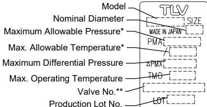
Refer to the product nameplate for detailed specifications. Minimum required condensate load for the SS1VG-M (metal valve seat) is 0.5 kg/h (1 lb/h) to maintain a liquid seal. The SS1VG-R requires 0 kg/h for tight sealing.
| Model | SS1VG-R (Rubber Orifice) | SS1VG-M (Metal Orifice) |
|---|---|---|
| Connection | Screwed | Screwed |
| Size | 1/2", 3/4", 1" | 1/2", 3/4", 1" |
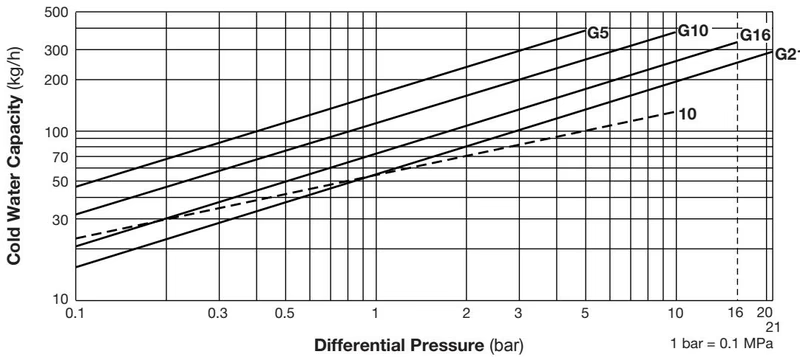
| Orifice No. | 10 | G5, G10, G16, G21 |
| Max Operating Pressure (barg) PMO | 10 | 5, 10, 16, 21 |
| Max Differential Pressure (bar) ΔPMX | 10 | 5, 10, 16, 21 |
| Max Operating Temperature (°C) TMO | 150 | 220 |
| Min Condensate Load (kg/h) | 0 | 0.5 |
| Applicable Fluid | Air, Inert Gas | Air, Inert Gas |
SS1VG-R (with rubber valve seat)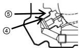
SS1VG-M (with metal valve seat)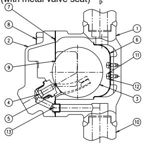
| No. | Name | No. | Name |
|---|---|---|---|
| 1 | Body | 8 | Cover Bolt |
| 2 | Cover | 9 | Nameplate |
| 3 | Float | 10 | Flange |
| 4 | Valve Seat (Orifice) | 11 | Screw |
| 5 | Valve Seat Gasket | 12 | Spring Washer |
| 6 | Screen | 13 | Connector |
| 7 | Cover Gasket |
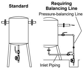
A visual inspection should be done on a daily basis to determine whether the product is operating properly. Periodically (at least biannually) the operation should also be checked by using diagnostic equipment.
| Part | Inspection Item |
|---|---|
| Gaskets | Check for warping or damage |
| Screen | Check for clogging, corrosion or damage |
| Valve Seat | Check for clogging, warping or scratches |
| Float | Check for scratches, dents or water inside the float |
| Body, Cover | Check for damage or build-up inside |
WARNING
When disassembling or removing the product, wait until the internal pressure equals atmospheric pressure and the surface of the product has cooled to room temperature.
Torque values for reassembly:
INFO
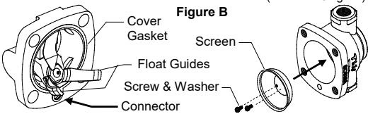
NOTE: Do not change the position of the float guides. Tight sealing cannot be guaranteed if the float guides have been moved out of position.
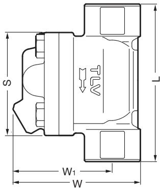
SS1VG Screwed
| Size | L (mm) | W (mm) | W1 (mm) | S (mm) | Weight (kg) |
|---|---|---|---|---|---|
| 1/2" | 110 | 103 | 82 | 85 | 1.6 |
| 3/4" | 120 | 103 | 82 | 85 | 1.7 |
| 1" | 130 | 103 | 82 | 85 | 1.8 |
Explore similar products in our catalog