IP67 Protection

Yoshitake BFV-1S high performance stainless steel butterfly valve with PTFE seat and double-eccentric structure. 50-300A for steam, air, water, and oil.
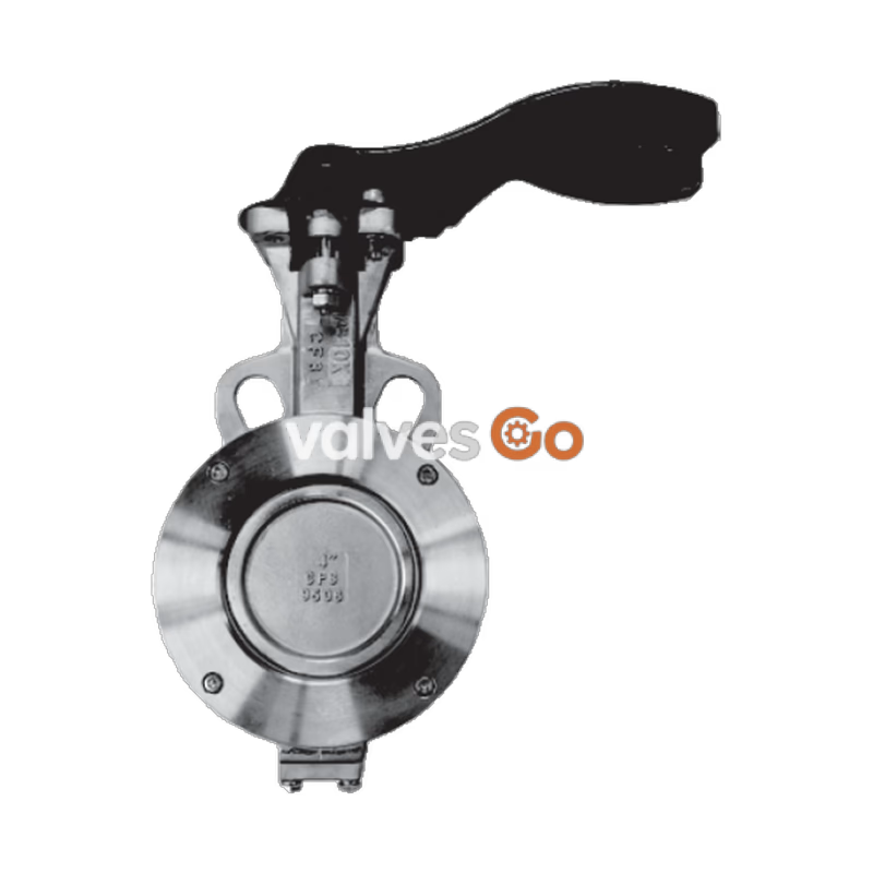
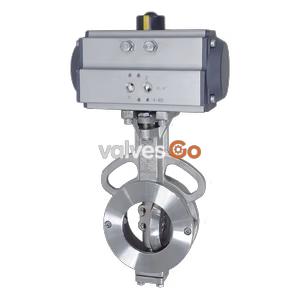
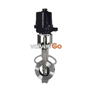
Yoshitake BFV-1S is a high performance butterfly valve featuring a stainless steel body and a PTFE seat. It utilizes a double-eccentric structure that provides excellent sealing and a long service life. The valve is designed for use with steam, air, water, oil, and other non-dangerous fluids, making it suitable for various industrial applications. Pneumatic actuator KA and electric actuator DA are mountable for sizes 50 to 150A.
| Item | Description |
|---|---|
| Model | BFV-1S |
| Nominal size | 50-150A (Lever-operated), 200-300A (Gear-operated) |
| Application fluid | Steam, air, water, oil and other non-dangerous fluids |
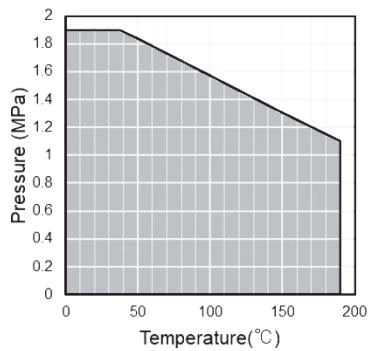
| Max. pressure / temperature | According to the Pressure-Temperature rating |
| Body Material | Stainless steel |
| Disc Material | Stainless steel |
| Seat Material | PTFE |
| Connection | Wafer (JIS 10K, ASME Class 150 / ANSI 150lb, EN PN16) |
WARNING
Confirm that the indications on the nameplate correspond with the specifications of the ordered product. Do not use the product if they are different.
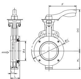
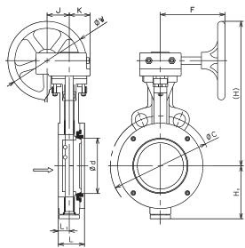
| Nominal size | d | L | L1 | H | H1 | F | C (JIS 10K) | C (EN PN16) | C (ANSI 150) | Weight (kg) |
|---|---|---|---|---|---|---|---|---|---|---|
| 50A | 50 | 43 | 18 | 212 | 72 | 210 | 120 | 125 | 120.5 | 3.5 |
| 65A | 59 | 49 | 22 | 227 | 80 | 210 | 140 | 145 | 139.5 | 4.5 |
| 80A | 72 | 49 | 22 | 237 | 87 | 210 | 150 | 160 | 152.5 | 5 |
| 100A | 96 | 54 | 23 | 252 | 102 | 210 | 175 | 180 | 190.5 | 7 |
| Nominal size | d | L | L1 | H | H1 | F | J | K | W | C (JIS 10K) | C (EN PN16) | C (ANSI 150) | Weight (kg) |
|---|---|---|---|---|---|---|---|---|---|---|---|---|---|
| 200A | 190 | 64 | 27 | 306 | 167 | 210 | 53 | 57 | 260 | 290 | 295 | 298.5 | 24 |
| 250A | 238 | 71 | 32 | 370 | 205 | 210 | 66 | 77 | 300 | 355 | 355 | 362 | 40 |
| 300A | 282 | 81 | 36 | 407 | 245 | 210 | 66 | 77 | 300 | 400 | 410 | 432 | 55 |
Attach the Handle with its tip pointing at the "SHUT" position, and fix it with a flat head screw. 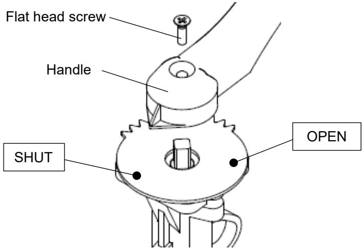
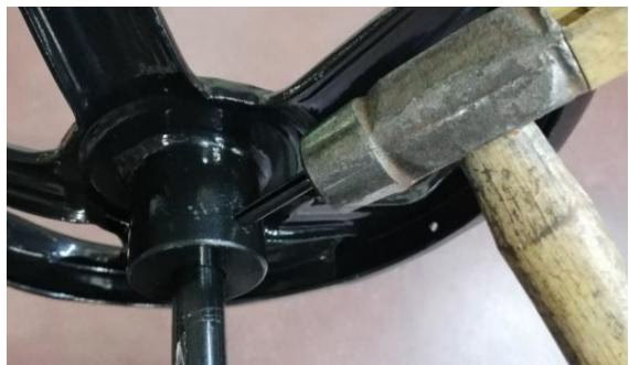
Align the holes of the Handle and the shaft. Insert the pin and hit it with a hammer to fix them. 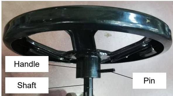
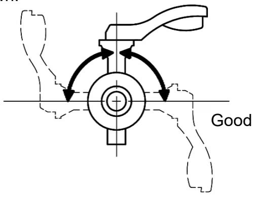
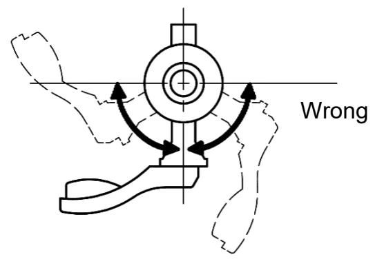
Installation Directions
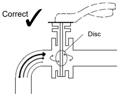
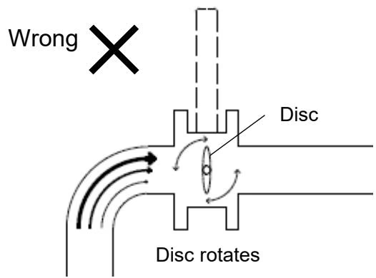
Piping and Connections
Improper Locations
Warning
Caution
Warning
When disassembling and inspecting the product, ensure that pressure in the valve and pipe is atmospheric pressure. If using with high temperature fluids, cool the product down well until it can be touched with bare hands. Disassembly and inspection should be conducted by properly trained personnel.
Conduct periodic inspection once a year to maintain functions and performance of the product.
| Inspection items |
|---|
| Whether opening and closing operation is normal |
| Whether there is abnormal noise |
| Whether there is external leak |
| Trouble | Cause | Remedy |
|---|---|---|
| External leak from the gland part | Nut is loose. | Tighten nut. If the leak does not stop, replace the product. |
| Seat leakage | Seat is damaged. | Replace the product. |
| Disc is damaged. | Replace the product. | |
| Foreign substances are stuck. | Remove the foreign substances. | |
| Abnormally high operation torque | Nut is overtightened. | Loosen nut and re-tighten so that there is no leak (but not too tightly). |
| Seat is damaged. | Replace the product. | |
| Foreign substances are stuck. | Remove the foreign substances. | |
| Abnormal noise | Nut is loose. | Tighten nut. |
Yoshitake Isolation Valves / Butterfly Valves
BFV and KBFV series butterfly valves for compact isolation and automated control on larger pipe sizes.
Explore similar products in our catalog