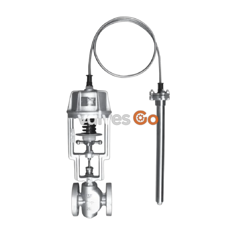
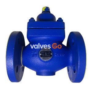
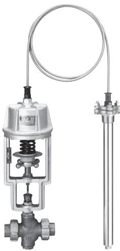
Yoshitake OB-3 is a direct acting temperature regulator valve designed for heating and cooling applications, suitable for cold and hot water, oil, refrigerants, and non-dangerous fluids. It features a bronze body and a phosphor bronze bellows, providing a temperature adjusting range of 40-120°C for both liquid and air. The related OB-3G model is available with an external pressure type bellows for applications where the ambient temperature exceeds the set temperature or is below 40°C.
Features
- Piping can be easily connected due to a union type connection screw.
- These temperature regulators do not require any adjusting tool because they are equipped with an adjusting handle which leads to easy adjustment.
- Since these temperature regulators adopt a dual-valve structure, the flow rate is larger than that of single-valve temperature regulators.
- Excellent accuracy since special packing is used for spindle gland packing which affects opening/closing operation of the valve.
- OB-3G ensures distinguished temperature resistance due to an external pressure type bellows.
Specifications
| Model | OB-3 | OB-3G |
|---|
| Application | Cooling / Heating | Cold water, Refrigerant / Cold and hot water, Oil, Non-dangerous fluid |
| Max. pressure (Body) | 0.7 MPa | 0.7 MPa |
| Max. pressure (Thermal valve) | 1.0 MPa | 1.0 MPa |
| Max. temperature | 180°C | 180°C |
| Temperature adjusting range (For liquid) | 40-120°C | 15-100°C |
| Temperature adjusting range (For air) | 40-120°C | 15-100°C |
| Ambient temperature | Set temp. -10°C or less | Set temp. +30°C or less |
| Material (Body) | Bronze | Bronze |
| Material (Valve, valve seat) | Bronze | Bronze |
| Material (Valve spindle) | Stainless steel | Stainless steel |
| Material (Bellows) | Phosphor bronze | Phosphor bronze |
| Material (Thermal valve - For liquid) | Stainless steel | Stainless steel |
| Material (Thermal valve - For air) | Stainless steel with fin | Stainless steel with fin |
| Standard capillary length | 2m | 2m |
| Connection | JIS Rc screwed (union joint) | JIS Rc screwed (union joint) |
Notes
- If the ambient temperature is higher than the set temperature or less than 40°C, use the OB-3G (with external pressure type bellows).
- Available with capillary of up to 5 meter.
- Available with temperature adjusting range of 30°C. (For OB-3 only).
- Available with thermal well (SUS304 made or with a PTFE cap) for liquid.
Temperature Adjusting Range
OB-3
| Temperature adjusting (°C) (For liquid) | Temperature adjusting (°C) (For air) | Withstand temperature (°C) |
|---|
| 40-60 | 40-60 | 70 |
| 50-70 | 50-70 | 80 |
| 60-80 | 60-80 | 90 |
| 80-100 | 80-100 | 110 |
| 100-120 | 100-120 | 130 |
OB-3G
| Temperature adjusting (°C) (For liquid) | Temperature adjusting (°C) (For air) | Withstand temperature (°C) |
|---|
| 15-35 | 15-35 | 50 |
| 20-40 | 20-40 | 50 |
| 35-55 | 35-55 | 70 |
| 40-60 | 40-60 | 90 |
| 50-70 | 50-70 | 100 |
| 60-80 | 60-80 | 110 |
| 70-90 | 70-90 | 120 |
| 80-100 | 80-100 | 130 |
INFO
The term "Withstand temperature" means the temperature from pressure resistance of the bellows.
Dimensions and Weights
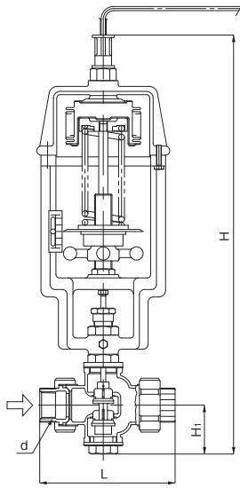
INFO
OB-3G has a little difference in bellows structure.
| Nominal size | d | L (mm) | H1 (mm) | H (mm) | Weight (kg) |
|---|
| 15A | Rc 1/2 | 148 | 55 | 510 | 11 |
| 20A | Rc 3/4 | 148 | 55 | 510 | 11 |
| 25A | Rc 1 | 160 | 60 | 520 | 12 |
| 32A | Rc 1-1/4 | 195 | 60 | 520 | 12 |
| 40A | Rc 1-1/2 | 210 | 65 | 530 | 13 |
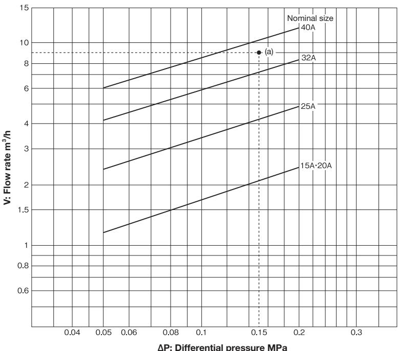
Nominal Size Selection Chart (For Water)
How to use the chart
When inlet pressure is 0.3 MPa, outlet pressure is 0.15 MPa, and flow rate is 9 m³/h, first find the intersection point (a) with the differential pressure (ΔP) 0.15 MPa (0.3 MPa - 0.15 MPa) before and after valve and the flow rate 9 m³/h. Since this intersection point (a) locates between nominal sizes 32A and 40A, select the larger one, 40A.
WARNING
Chart of the flow rate is a reference value.
Temperature Accuracy from Set Point
Depending on capillary length:
| Standard capillary length | OB-3 (For liquid) | OB-3 (For air) | OB-3G (For liquid, For air) |
|---|
| 2m | ± 2°C | ± 3°C | ± 3.5°C |
| 2-3.5m | ± 2.5°C | ± 3.5°C | ± 4°C |
| 3.5-5m | ± 3°C | ± 4°C | ± 4.5°C |
INFO
- If the preset temperature is higher than 100°C, add ± 1.0°C
- The preset temperature error is the maximum temperature width ranging from the time when the valve closes until the time when the valve starts to open, not the value expressing the control width.
Cv Value
| Nominal size | 15A | 20A | 25A | 32A | 40A |
|---|
| OB-3 / 3G | 2 | 2 | 4 | 7 | 10 |
Valve Seat Leakage
Unit: steam (kg/h), water (L/h)
| Nominal size | 15A | 20A | 25A | 32A | 40A |
|---|
| OB-3 / 3G | 1.5 | 1.5 | 1.8 | 2.4 | 3.0 |
INFO
The values in the table above are max. Valve seat leakage is measured under the condition of 0.5MPa or max.pressure at the temperature of "set temperature-5°C" for cooling.
Maintenance and Inspection
Cautions Before Use
Caution
- Do not disassemble the product without reason. If you disassemble the product for no reason, the original performance of the product is not achieved.
- When plumbing the product, make sure to remove foreign substances, scale, etc. from the pipes.
- Make sure to install a strainer (60 to 80 mesh) on the inlet side of the product.
- Install pressure gauges on the inlet and outlet sides of the product to confirm the operation of the product.
- To install the product, confirm the inlet, outlet and posture of the product.
- Install the product in a place where the temperature does not exceed the preset temperature.
- Install a thermometer near the thermal bulb.
- Install the thermal bulb in a way that makes three fourths or more of its total length come into contact with the fluid to be heated.
- Make sure that the installation posture of the thermal bulb is correct. If there are T marks on the flanges or joint nuts, follow the instructions on how to install them.
- The bending radius of the capillary tube must be 40 mm or more. Do not bend it at an acute angle, nor twist it or pull it forcibly.
Installation of Main Unit
- Install the temperature regulator valve vertically against the horizontal pipe, placing its frame above.
- If the ambient temperature becomes higher than the preset temperature, it may cause malfunction of the product, so install the product in a place where the temperature does not exceed the preset temperature.
- Make sure to install a pressure gauge and a strainer bypass pipe in the piping.
- If the pressure of the heating fluid is higher than the maximum pressure, use the product after reducing the pressure with the pressure reduction valve, etc.
- Implement the plumbing in a way that does not add excessive load, bending force, vibration, etc. to the main unit.
- If the product is to be left unused for a long time, completely drain the pipes and close the gate valves at the front and the rear of the temperature adjustment valve.
- When supplying air or water, make sure to remove foreign substances from the pipes through the bypass pipe and then open the temperature adjustment valve circuit.
Adjustment Procedures
Incorrect adjustment may cause hunting, scale problems or water hammer, and may heavily damage the main parts of the product. Be sure to follow the steps below.
- Close the stop valves at the front and the rear of the product. Open the bypass stop valve and blow fluid through the bypass line with enough time. After discharging, be sure to close the bypass stop valve. While blowing, be careful not to apply fluid of higher temperature than the max. allowable temperature of the product.
- Turn the handle and move the indicator to the desired temperature position on the scale. To raise the temperature, turn the handle counterclockwise (when seen from the top). To lower the temperature, turn it clockwise (when seen from the top). Reading scale is only for reference, so please adjust the temperature by using a thermometer.
- Slowly open the inlet stop valve to its full open position, and then, open the outlet stop valve little by little to its full open position.
- Adjust the handle till the desired temperature is obtained while watching the thermometer with enough time.