Cast Iron

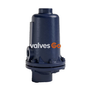
The Yoshitake TSF-8AT is a ductile cast iron float type air trap designed for condensate drainage in air and other non-dangerous fluid lines, featuring stainless steel internals and a maximum temperature of 220℃.
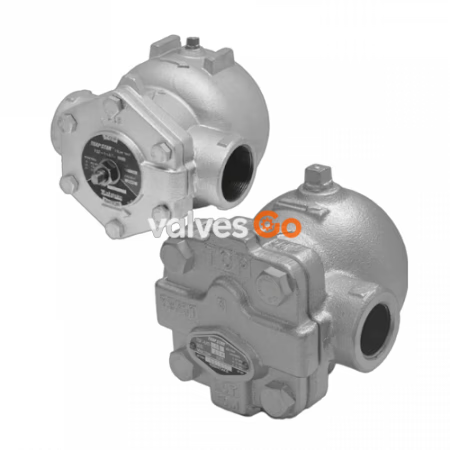
The Yoshitake TSF-8AT is a lever float type air trap designed to effectively discharge condensate from air and other non-dangerous fluid lines. Utilizing the difference in specific gravity between air and condensate, it operates reliably without retention. The main internal parts, including the float and valve, are constructed from stainless steel for excellent corrosion resistance and durability.
| Model | TSF-8AT |
|---|---|
| Nominal size | 15A, 20A, 25A |
| Application | Condensate (Air, Other non-dangerous fluid) |
| Working pressure | TSF-8AT-5: 0.01-0.5 MPa (0.5 MPa) TSF-8AT-10: 0.01-1.0 MPa (1.0 MPa) TSF-8AT-21: 0.01-2.1 MPa (2.1 MPa) |
| Max. temperature | 220℃ |
| Body | Ductile cast iron |
| Float | Stainless steel |
| Valve, valve seat | Stainless steel |
| Connection | JIS Rc, NPT screwed |
The standard flow direction of TSF-8AT is left to right. However, flow direction from right to left is also available.
| Flow direction | Symbol |
|---|---|
| Left to Right (Pre-set) | Blank |
| Right to Left | R |
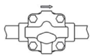 Left to Right: No symbol
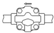 Right to Left: Symbol "R"
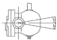
Installation Posture
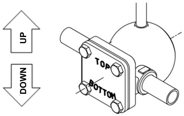
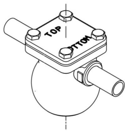
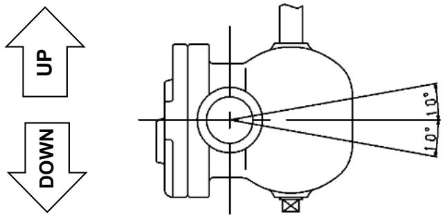
Allowable tilt from horizontal line is within ±10°. Wrong posture hampers proper operation.
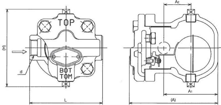
| Nominal size | d | L | A | A1 | H | Plug | Weight |
|---|---|---|---|---|---|---|---|
| 15A | Rc or NPT 1/2 | 121 | 147 | 90 | 145 | Rc or NPT 3/8 | 3.7 |
| 20A | Rc or NPT 3/4 | 121 | 147 | 90 | 145 | Rc or NPT 3/8 | 3.7 |
| 25A | Rc or NPT 1 | 145 | 147 | 90 | 145 | Rc or NPT 3/8 | 4.1 |
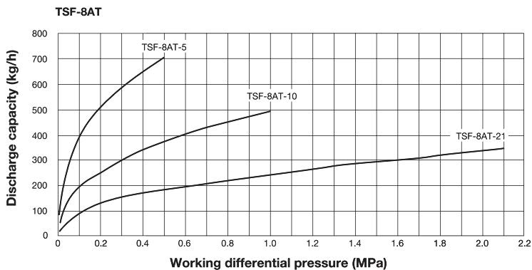
The discharge capacity shown on the above chart is the maximum value. In designing a system, select an air trap with a sufficient safety factor (more than two times the regular level).
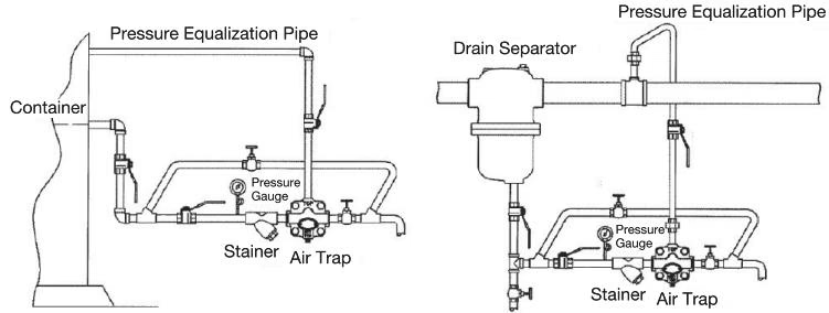
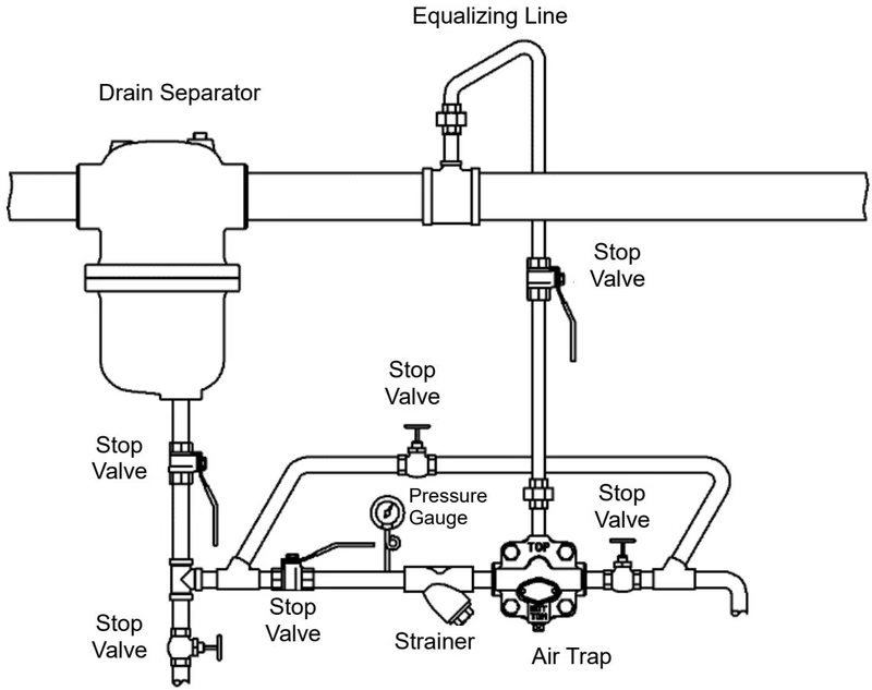
Piping Recommendations
*Remove the plug on the "TOP" side and install an equalizing line.
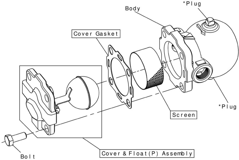
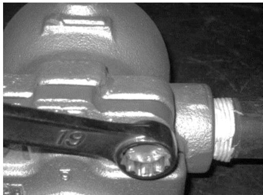
Loosen the bolts fixing the cover with a ring wrench (width across flat: 19 mm), and remove the cover and gasket from the body. Pull out the screen from the body.
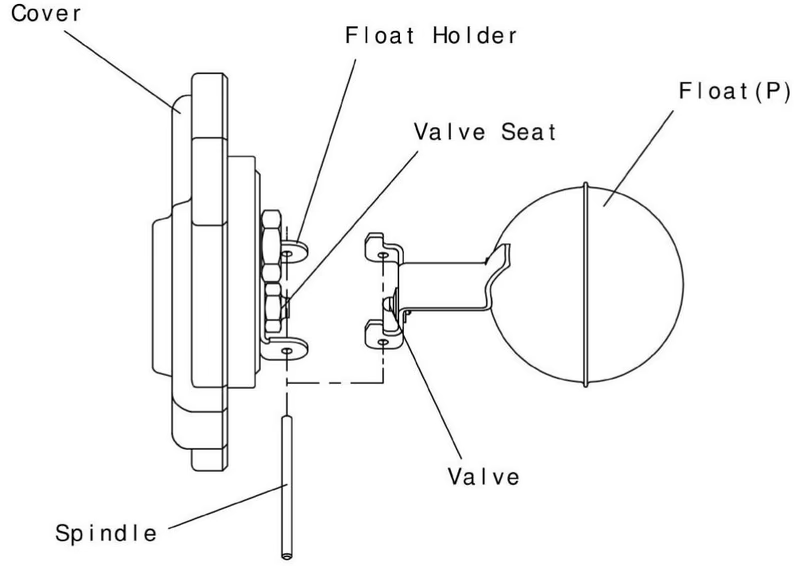
Connect the float holder and float (P) assembly with the spindle. Check that the float (P) assembly moves smoothly, and that the seat surface of the valve is in contact with that of the valve seat.
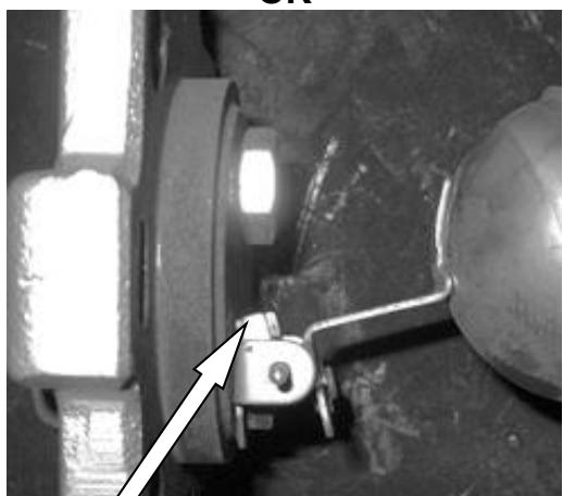 The stopper is on the center of the cock.
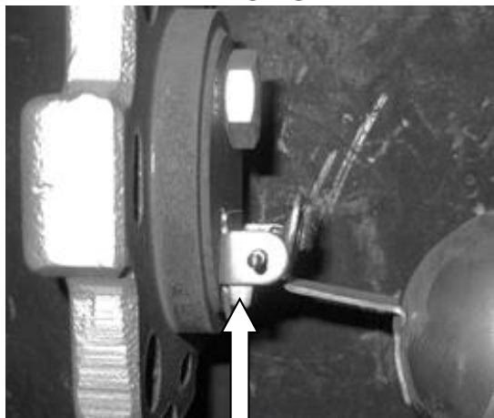 WRONG: The stopper is on the outer circumference of the cock.
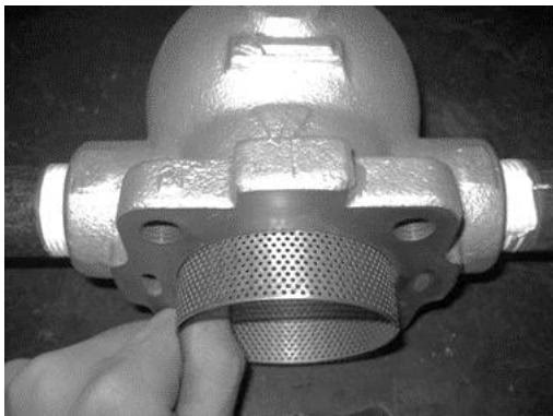
Attach the screen to the body. The screen can be inserted from either end.
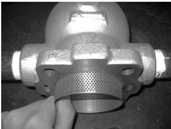
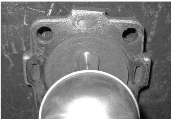
Install the cover gasket to the cover. Make the oval-shaped holes on the cover and on the cover gasket in the same position. Make sure to use a new cover gasket. Apply lubricant agent to the cover gasket.
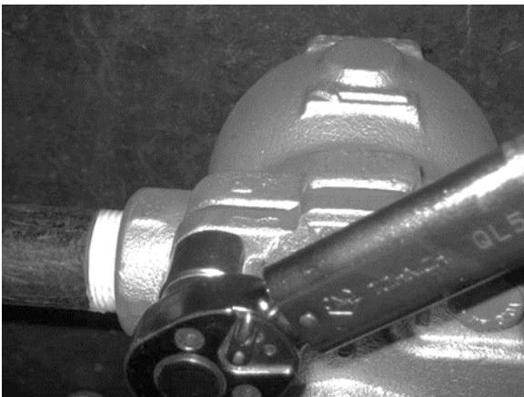
Install the cover to the body. Tighten the bolt with a torque wrench (width across flat: 19 mm) with torque of 45 N・m. Do not use an impact wrench.
Yoshitake Compressed Air Drain Traps
LD and TSF-AT series compressed-air drain traps for automatic condensate removal from air systems.
Explore similar products in our catalog