


PN25

BURKERT 20014131 (Type 2101) is a pneumatically operated 2/2-way NC globe valve with DN 25 PN25 flange, stainless steel 316L body, PTFE seat seal, 13 m³/h Kv, and 0–16 bar operating pressure for liquid and steam systems.
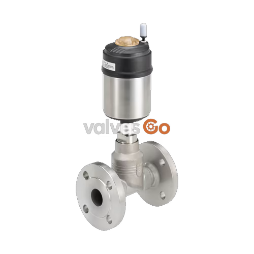
BURKERT 20014131 (Type 2101) is a pneumatically operated 2/2-way globe valve configured with a DN 25 DIN EN 1092-1 PN 25 flange connection, normally closed control function A, and flow direction below the seat. Built within the modular ELEMENT architecture, this valve is engineered for decentralised process automation, accommodating demanding media such as steam, water, alcohols, fuels, hydraulic fluids, saline solutions, and organic solvents. The assembly combines a precision-cast stainless steel 316L body with a 70 mm diameter polyphenylene sulphide (PPS) actuator, delivering tight shut-off up to 16 bar(g) and a water flow coefficient (Kv) of 13 m³/h.
Sealing integrity relies on a self-adjusting PTFE V-ring packing gland with spring compensation and a pivoting stainless steel swivel plate fitted with a PTFE seat seal. The valve meets DIN EN 12266-1 leakage rate A requirements. The actuator housing provides IP65/IP67 ingress protection, NEMA 4X classification, and chemical washdown resistance. The device complies with Regulation (EC) 1935/2004 for food contact and supports both clean-in-place (CIP) and steam-in-place (SIP) thermal decontamination cycles.
| Specification Parameter | Value / Range |
|---|---|
| Product Model / Series | 20014131 / Type 2101 |
| Valve Construction | Complete 2/2-way globe valve |
| Nominal Diameter (Seat & Connection) | DN 25 (NPS 1), Seat Diameter 25 mm |
| Flange Standard & Pressure Rating | DIN EN 1092-1, PN 25 (Face-to-face FTF 1 per DIN EN 558-1) |
| Control Function | Control function A (CFA): Normally closed (NC) by spring force |
| Flow Direction | Against closing direction (below seat) |
| Operating Pressure Range | 0.00 bar(g) to 16.00 bar(g) (derated at elevated temperatures) |
| Nominal Pressure Class | PN 25 (DIN EN 1333) / Class 150 (DIN EN 1759) |
| Pilot Pressure Range | 4.8 bar(g) to 10.0 bar(g) |
| Flow Coefficient (Kv water) | 13.0 m³/h (measured at +20 °C, 1 bar Δp) |
| Seat Leakage Class | Leakage rate A per DIN EN 12266-1 (Air test medium) |
| Medium Temperature Range | -40 °C to +185 °C (standard PTFE seat seal) |
| Ambient Temperature Range | -10 °C to +100 °C (with push-in pilot air port) |
| Maximum Medium Viscosity | 600 mm²/s |
| Control Medium | Neutral gases, compressed air |
| Pilot Air Connection | Push-in connector for hose external Ø 6 mm (G 1/8 available) |
| Ingress Protection & Rating | IP65 / IP67 according to IEC 529 / EN 60529, NEMA Type 4X |
| Conformity & Directives | Pressure Equipment Directive 2014/68/EU, Machinery Directive 2006/42/EC |
| Food Contact Compliance | Regulation (EC) 1935/2004, FDA compliant materials, CIP / SIP capable |
Type 2101 uses a pneumatic piston actuator acting directly on a valve spindle and swivel plate. In control function A, internal spring sets press the swivel plate against the screwed-in valve seat when de-energised. Supplying pilot pressure (minimum 4.8 bar) beneath the actuator piston lifts the spindle to open the flow path.

In model 20014131, flow enters below the seat. Operating pressure acts on the underside of the swivel plate, assisting the opening stroke and preventing pressure spikes.
WATER HAMMER HAZARD ON FLOW-ABOVE-SEAT VARIANTS
Do not use valves configured with flow direction above the seat for liquid mediums. In liquid services, closing with the medium flow induces water hammer, leading to fractured pipework and device destruction. Flow-above-seat configurations are restricted strictly to dry gases and steam.
All wetted metallic components are manufactured from stainless steel 316L (CF3M) and 1.4404. Non-metallic seals contacting media are certified virgin PTFE and fluoroelastomers.
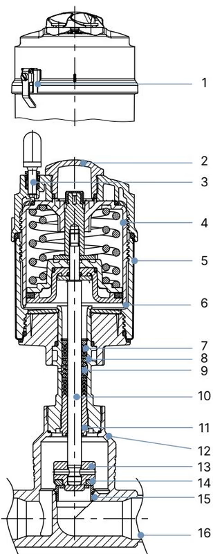
| Item No. | Component Description | Material Specification |
|---|---|---|
| 1 | Ground Terminal (ATEX variant) | Stainless steel 1.4301 / 1.4305 |
| 2 | Optical Position Indicator | Polysulfone (PSU) |
| 3 | Pilot Air Ports | Polypropylene (PP) push-in standard; G 1/8 stainless steel 1.4305 optional |
| 4 | Actuator Cover | Polyphenylene sulphide (PPS) |
| 5 | Actuator Casing | Stainless steel 1.4561 (316Ti) |
| 6 | Piston Seal | Fluoroelastomer (FKM) |
| 7 | Actuator Spring Set | Stainless steel 1.4310 |
| 8 | Spindle Packing Tube | Stainless steel 1.4401 (316) / 1.4404 (316L) |
| 9 | Spindle Packing Gland | Filled PTFE V-rings with Belleville spring compensation |
| 10 | Valve Spindle | Stainless steel 1.4401 (316) / 1.4404 (316L) |
| 11 | Spindle Guide Bushing | Polyetheretherketone (PEEK) for DN 15–65 |
| 12 | Body Flange Seal | Graphite (PTFE optional) |
| 13 | Swivel Plate | Stainless steel 1.4401 (316) / 1.4404 (316L) |
| 14 | Valve Seat Seal | PTFE (Polytetrafluoroethylene) |
| 15 | Screwed-in Valve Seat | Stainless steel 1.4571 with EPDM O-ring |
| 16 | Valve Body | Cast stainless steel CF3M / forged 316L |
All lubricants applied to the actuator piston seal and spindle packing are classified according to NSF H1 for incidental food contact.
Model 20014131 features a DN 25 flanged body conforming to DIN EN 1092-1 PN 25, face-to-face dimension FTF 1 (DIN EN 558-1). The Ø 70 mm PPS actuator provides necessary thrust while maintaining a compact vertical profile.
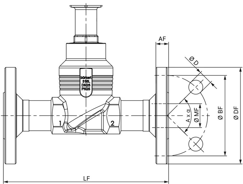
| Connection DN | Outer Flange Ø DF [mm] | Face-to-Face LF [mm] | Pitch Circle Ø BF [mm] | Flange Thickness AF [mm] | Hole Diameter Ø D [mm] | Bolt Pattern A x α | Raised Face Ø MF [mm] |
|---|---|---|---|---|---|---|---|
| 10 | 90 | 130 | 60 | 16 | 14 | 4 × 90° | 13.6 |
| 15 | 95 | 130 | 65 | 16 | 14 | 4 × 90° | 18.1 |
| 20 | 105 | 150 | 75 | 18 | 14 | 4 × 90° | 23.7 |
| 25 (Model 20014131) | 115 | 160 | 85 | 18 | 14 | 4 × 90° | 29.7 |
| 32 | 140 | 180 | 100 | 18 | 18 | 4 × 90° | 38.4 |
| 40 | 150 | 200 | 110 | 18 | 18 | 4 × 90° | 44.3 |
| 50 | 165 | 230 | 125 | 20 | 18 | 4 × 90° | 56.3 |
The maximum permissible working pressure decreases with increasing operating temperature in compliance with DIN EN 12516-1.
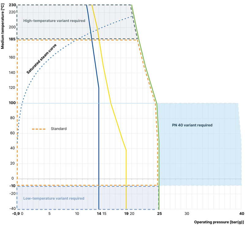
| Medium Temperature [°C] | Permissible Operating Pressure [bar] |
|---|---|
| -10 °C to +50 °C | 25.0 bar |
| +100 °C | 24.5 bar |
| +150 °C | 22.4 bar |
| +185 °C (Upper limit for PTFE seat) | 21.0 bar |
| +200 °C | 20.3 bar |
| +230 °C (PEEK seat variant only) | 19.0 bar |
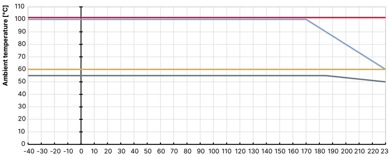
AMBIENT AND MEDIUM TEMPERATURE INTERDEPENDENCE
When operating at a maximum medium temperature of +185 °C, ensure ambient temperature does not exceed +60 °C when using polymer push-in pneumatic fittings, or +100 °C when using metallic threaded pilot connections. When an electrical pilot solenoid is mounted directly on the actuator, ambient temperature is limited to +55 °C.
Before mounting, ensure pipelines are fully blown down, free of weld spatter, slag, and debris. Cleanliness protects the ground seat sealing face from scoring.
360° ACTUATOR POSITIONING
The pneumatic actuator can be rotated 360° independently of the valve body to orient pilot air connections and cable glands away from obstructions:
RELIEF BORE LEAKAGE MONITORING
The bonnet tube features an integrated relief bore between the primary spindle packing and actuator wiper seals. An optional adapter kit converts this port to an M4 or M5 thread, allowing users to fit leak detection pressure transmitters or drainage piping. Never seal this port with a closed plug, as backpressure can force process fluid directly into the pneumatic chamber.
Under normal service conditions, the actuator requires no lubrication or internal maintenance. Routine preventative checks include periodic inspection of the relief bore for weeping fluid, which signals early packing gland wear.
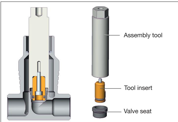
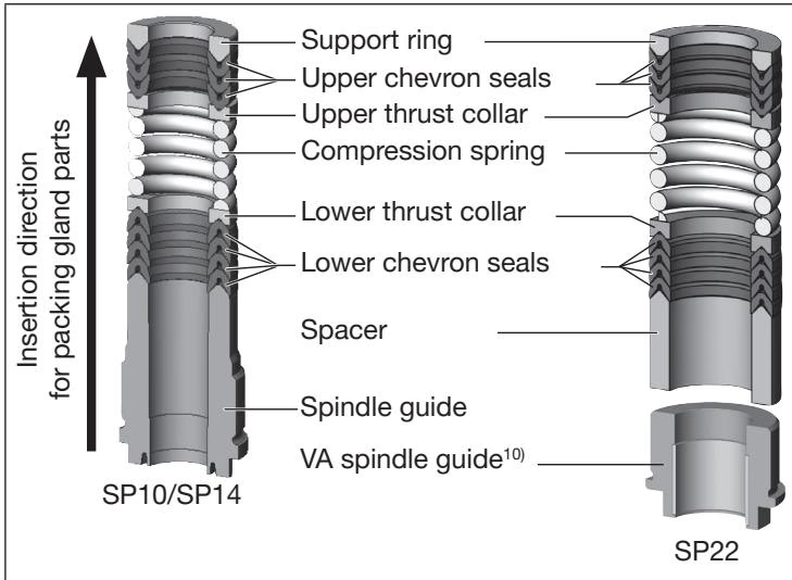
The packing gland seal set contains 1 support ring, 7 chevron V-rings, 2 thrust collars, 1 Belleville compression spring, 1 PEEK spindle guide, and body seals.
| Description of Spare Part Set | Orifice / Size | Bürkert Order Number |
|---|---|---|
| Valve Set (Swivel plate with PTFE seal, pin, body seal) | DN 25 | 160 737 |
| Seal Set for Packing Gland (Standard PTFE V-rings) | DN 15–50, Actuator Ø 70 mm | 216 433 |
| Seal Set for Packing Gland (Hot water variant up to +200 °C) | DN 15–50, Actuator Ø 70 mm | 372 661 |
| Seal Set for Packing Gland (High temp variant up to +230 °C) | DN 15–50, Actuator Ø 70 mm | 372 662 |
| Valve Seat Set (Seat, O-ring, body seal) | DN 25 | 262 170 |
| Seat Assembly Tool | DN 25 | 652 606 |
| Modified Socket Wrench for Spindle Guide | DN 15–50 (Spindle Ø 10 mm, AF 19) | 683 221 |
Model 20014131 integrates directly with Burkert ELEMENT control tops without external pipework, routing pneumatic pilot air through internal channels:
Explore similar products in our catalog



