

PN16

BURKERT 20047407 is a Type 8640 modular pneumatic valve block with 19 mm station width, G 1/4 supply ports, D6 push-in working ports, 2 to 10 bar operating pressure, and DIN-rail mounting.
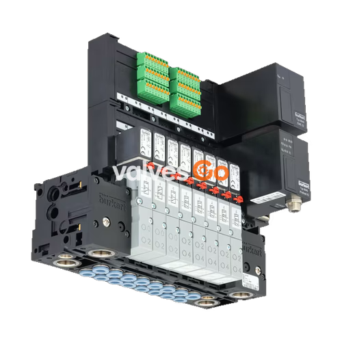
BURKERT 20047407 (Type 8640) is a modular valve block for pneumatics configured with a 19 mm width per station, G 1/4 supply connections, and D6 push-in working ports. The unit mounts Type 5470 solenoid pilot valves onto MP05 base modules to form compact valve groups for controlling neutral gases and compressed dry air. Operating across a pressure range of 2.0 to 10.0 bar, the assembly delivers a nominal flow rate of 300 l/min at 6 bar inlet pressure and 1 bar differential pressure. The configuration operates without an internal communication bus, utilizing individual wiring for each valve station via cable plug interfaces.
Designed for mechanical integration into industrial control panels, BURKERT 20047407 supports standard DIN-rail mounting according to EN 50022 (35 × 7.5 mm or 35 × 15 mm) as well as direct wall mounting. The standard valve terminal achieves an IP20 ingress protection rating, which extends to IP65 when fitted with Type 2516 cable plugs. Media temperature is rated from 0 °C to +50 °C, with ambient operating limits spanning 0 °C to +55 °C.
| Technical Property | Value / Specification |
|---|---|
| Product Type | Type 8640 modular valve block |
| Article Number | 20047407 |
| Integrated Valve Type | Type 5470 rocker pilot valve with Type 6106 actuator |
| Width per Station | 19 mm |
| Supply Port 1 (P), Exhaust Ports 3 (R), 5 (S) | G 1/4 |
| Working Ports 2 (B), 4 (A) | D6 (push-in coupling for ∅ 6 mm tubing) |
| Operating Pressure Range | 2.0 to 10.0 bar |
| Pilot Pressure Requirement | 2.0 to 10.0 bar (at least 70% of operating pressure) |
| Pressure Difference (Port 1 to 3) | Minimum 2.0 bar |
| Nominal Flow Rate $Q_{Nn}$ (Air) | 300 l/min (+20 °C, 6 bar inlet, 1 bar Δp) |
| Nominal Operating Mode | Continuous operation (100% duty cycle) |
| Operating Medium | Filtered dry compressed air (≤ 5 µm), neutral gases |
| Air Quality Standard | ISO 8573-1:2010, Class 7.4.4 |
| Medium Temperature | 0 °C to +50 °C (down to -10 °C with dried air) |
| Ambient Temperature | 0 °C to +55 °C |
| Storage Temperature | -40 °C to +55 °C |
| Valve Body Material | Polyamide (PA) |
| Seal Material | Nitrile butadiene rubber (NBR) |
| Operating Voltage | 24 V DC (±10% tolerance, ripple ≤ 1 Vss) |
| Nominal Power per Valve Coil | 1 W, 2 W, or 3 W depending on coil specification |
| Degree of Protection | IP20 (IP65 with Type 2516 cable plug) |
| Electrical Interface | Single wiring, DIN EN 175301-803 Form C |
| Internal Bus Communication | None (individual wiring) |
| Installation Orientation | Any, preferably with solenoid actuator upright |
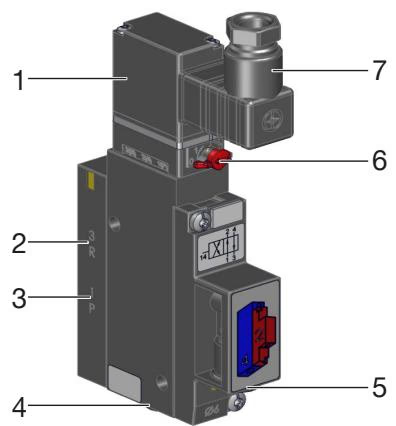
The Type 5470 valve consists of a pneumatic valve body fitted with a Type 6106 rocker pilot valve. Inside the pilot valve, an armature with a tilting bearing rocks back and forth to switch pilot air paths. The rocking movement requires no basic lubrication and operates without frictional wear. Working connections 2 (B) and 4 (A), supply channel 1 (P), and exhaust channel 3 (R) are integrated into the modular base rail interface.
Each valve position features a manual override switch located on the valve front. To lock the valve into the energized switching position manually, depress the override button and turn it 90° clockwise until it hits the mechanical stop. The override locks in place and will not reset automatically.
Manual Override Precaution
Operate the manual override only when electrical supply voltage is disconnected. Disengage the manual override to the zero position before resuming normal electrical automation.
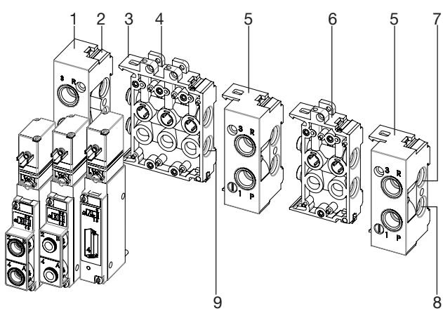
The valve block is constructed using modular MP05 pneumatic segments:
To assemble multiple base blocks, lightly lubricate all channel O-rings with grease or oil. Insert the two O-rings into the module lateral face, engage the lower latch hooks into the grooves of the preceding block, tilt the module upward, and snap the upper latch hook firmly into place. Secure each Type 5470 valve to its base station with two M2 fastening screws tightened to 0.6 ±0.1 Nm torque. Always ensure the three individual O-rings are correctly seated in the rear valve recess before bolting down the valve body.
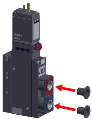
A 4/2-way Type 5470 valve can be converted into a 3/2-way function by sealing one of the active working ports with a dedicated stopper plug:
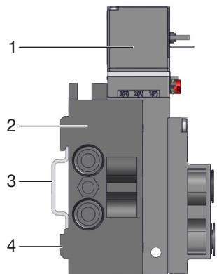
The assembled valve terminal can be mounted directly onto an EN 50022 top-hat rail (35 × 7.5 mm or 35 × 15 mm) or fastened directly to a flat cabinet wall using M4 screws.
| Port Thread Size | Function / Channel Designation | Recommended Torque | Maximum Permissible Torque |
|---|---|---|---|
| G 1/4 / NPT 1/4 | Supply port 1 (P), exhaust port 3 (R/S) | 4 to 7 Nm | 20 Nm |
| G 1/8 / NPT 1/8 | Service ports 2 (B), 4 (A) | 3 to 6 Nm | 7 Nm |
Pilot Solenoid Orientation
If the cable plug orientation conflicts with adjacent components, the solenoid coil can be rotated by 180°. Remove the M2 fastening screw, rotate the coil, place it back onto the valve guide tube, and tighten the screw in two increments: first to 0.1 ±0.05 Nm, then to 0.2 ±0.05 Nm.
Pneumatic lines must comply with DIN 73378 outside diameter tolerances and have a minimum material hardness of 40 Shore D according to DIN 53505 / ISO 868. Hose ends must be cut straight at a 90° angle without burrs or external surface gouges.
| Tubing Outer Diameter | Minimum Tensile Force (PA Hose) | Minimum Tensile Force (PU Hose) |
|---|---|---|
| 3 mm (1/8") | 60 N | 25 N |
| 4 mm (5/32") | 70 N | 50 N |
| 6 mm (1/4") | 120 N | 100 N |
| 8 mm (5/16") | 170 N | 150 N |
| 10 mm (3/8") | 250 N | 200 N |
Tube Support Sleeves
When using flexible polyurethane (PU) tubing under high operating pressures or elevated ambient temperatures, insert internal support sleeves (article 20099400) into the tubing ends prior to insertion to prevent line leakage or pull-out.
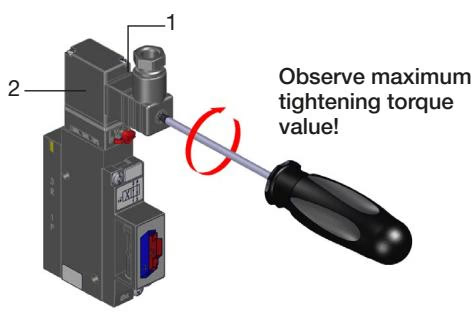
Single wiring electrical connectivity is established using individual cable plugs conforming to DIN EN 175301-803 Form C (such as Type 2516 or Type 2506). Ensure the flat gasket is positioned between the plug and the coil contact face, and tighten the central retaining screw to a maximum torque of 0.3 Nm. Always verify electrical continuity between the protective earth terminal and the valve block housing (maximum resistance 0.1 Ω at 12 V / 1 A test current).
Before undertaking any servicing or disassembly work, depressurize the pneumatic system, vent the main supply pipes, and switch off electrical power.
| Fault Condition | Root Cause | Corrective Action |
|---|---|---|
| Valves fail to switch | No supply voltage or operating voltage below tolerance | Verify 24 V DC power supply at plug terminals against label specifications. |
| Manual override locked in engaged position | Rotate manual override 90° counterclockwise back to zero position. | |
| Operating supply pressure below 2.0 bar | Increase supply line pressure to minimum 2.0 bar; check upstream pressure regulators. | |
| Delayed valve switching or continuous exhaust blow-off | Supply volume inadequate or line cross-section restricted | Ensure supply piping has adequate volume and cross section; maintain ≥ 2.0 bar under flow. |
| Block pressurized while valves were already electrically actuated | Apply pneumatic pressure to the island before switching individual valve solenoids. | |
| Exhaust ports choked due to clogged silencers | Clean or replace contaminated silencers; verify back-pressure is relieved. | |
| Contaminants lodged within pilot or main seat | Apply pressure pulses through exhaust ducts to dislodge particles, or replace defective valve. | |
| External leakage between modules | Damaged, pinched, or missing inter-module O-rings | Disassemble module sub-block, replace defective O-rings, and verify correct seat alignment. |
| Leakage beneath valve body | Valve mounting screws loose or rear O-rings misaligned | Reinstall valve, replace rear seal rings, and tighten M2 screws to 0.6 ±0.1 Nm. |
Explore similar products in our catalog


