


PN25

Burkert 20078458 (Type 2100) is a pneumatically operated 2/2-way angle seat valve featuring DN65 ASME BPE clamp connections, CFB normally open operation, PTFE seat sealing, and PN25 stainless steel construction.
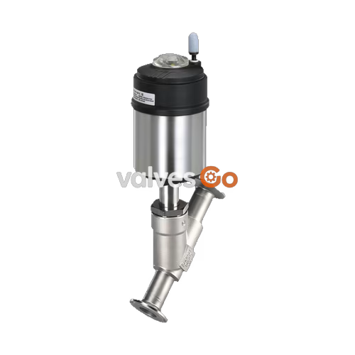
BURKERT 20078458 (Type 2100) is a pneumatically operated 2/2-way angle seat valve engineered for decentralized process automation in hygienic and industrial fluid networks. Configured with control function B (normally open), the valve opens via internal spring force in its rest position and shuts off when compressed air is supplied to the pilot port. The process connection conforms to the ASME BPE clamp standard in nominal size DN65 (2 1/2 in), featuring a precision cast CF3M stainless steel body, PTFE seat seal, and a self-adjusting packing gland with spring-compensated PTFE V-rings. Delivering a water flow coefficient Kv of 85 m³/h across an installation face-to-face length of 286 mm, the assembly handles media pressures up to 16 bar and temperatures ranging from -10 °C to +185 °C.
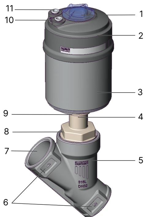
Compatibility with CIP and SIP cleaning regimens, compliance with EC 1935/2004 and FDA food contact standards, and mechanical ATEX / IECEx certification (II 2 G Ex h IIC T4...T2 Gb, II 2 D Ex h IIIC T135°C...T300°C Db) allow deployment in pharmaceutical processing, food and beverage lines, and potentially explosive Zone 1/21 and 2/22 plant environments. The ELEMENT platform architecture integrates pilot air routing directly into the PPS actuator housing and supports the mounting of decentralized automation heads and position indicators.
| Specification Parameter | Value |
|---|---|
| Article Number | 20078458 |
| Valve Type / Platform | Type 2100 ELEMENT |
| Construction | 2/2-way complete angle seat valve |
| Control Function | Control function B (CFB), normally open (NO) |
| Fluidic Ports | 2 ports, 2 switching positions |
| Nominal Diameter (DN) | DN 65 (2 1/2") |
| Seat Diameter | 65 mm |
| Flow Coefficient Kv (Water) | 85 m³/h |
| Process Connection Type | Hygienic Clamp connection |
| Pipe Standard / Sizing | ASME BPE (Clamp OD 77.5 mm / 3.047", Tube OD 63.5 mm / 2.5", Tube ID 60.2 mm, Wall 1.65 mm) |
| Face-to-Face Installation Length | 286 mm |
| Body Material | Cast stainless steel CF3M |
| Seat Seal Material | PTFE (Polytetrafluoroethylene) |
| Spindle / Swivel Plate Material | Stainless steel 1.4401 / 1.4404 |
| Spindle Guide Bushing | PEEK |
| Packing Gland | Self-adjusting PTFE V-rings with spring compensation (lubricated with silicone grease) |
| Actuator Housing Material | PPS (Polyphenylene sulphide) and stainless steel |
| Actuator Size | 130 (P) |
| Pilot Air Connection | Push-in connector 6/4 mm (Interface ELEMENT) |
| Operating Pressure Range | 0 to 16 bar (PN 25 / ASME Class 150 derating applies) |
| Pilot Pressure Range | 2.5 to 7.0 bar |
| Control Medium | Neutral gases, air |
| Permissible Process Media | Water, alcohol, oils, fuels, hydraulic fluids, saline solutions, lyes, organic solvents, steam, neutral gases |
| Medium Temperature Range | -10 °C to +185 °C |
| Ambient Temperature Range | -10 °C to +100 °C (threaded ports) / -10 °C to +60 °C (push-in connector) |
| Storage Temperature | -20 °C to +65 °C |
| Enclosure Protection Rating | IP67 (EN/IEC 60529), NEMA 4X |
| Sound Pressure Level | < 70 dB(A) |
| Hygienic Compliance | CIP capable, SIP capable, EC 1935/2004, FDA compliant |
| Explosion Protection | ATEX / IECEx: II 2 G Ex h IIC T4...T2 Gb, II 2 D Ex h IIIC T135°C...T300°C Db |
BURKERT Type 2100 with control function B utilizes pilot pressure to overcome the actuator spring force and close the valve swivel plate against the valve seat. In the unpressurized rest position, the pre-tensioned actuator springs hold the spindle and swivel plate in the fully open state.
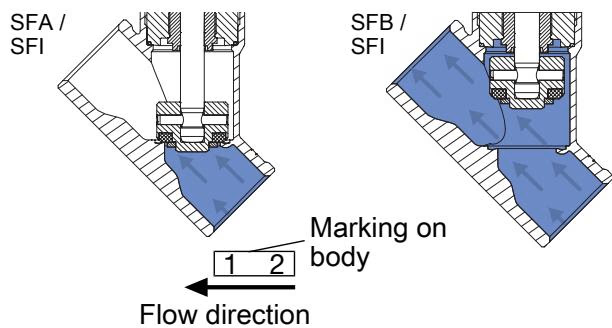
The unit is configured exclusively for flow direction below the seat. Medium enters from under the swivel plate, allowing operating pressure to assist the opening stroke and preventing hydraulic pressure surges (water hammer) in liquid piping lines:
Operating Pressure and Pilot Air Requirement
For control function B with flow direction below the seat, operating pressure opposes the closing force. To ensure shut-off tightness across the valve seat, pilot pressure must be maintained within the specified range (2.5 to 7.0 bar) and verified against actual line operating pressures.
The operating pressure and permissible ambient temperatures depend on the medium temperature and the type of pneumatic port fittings installed.
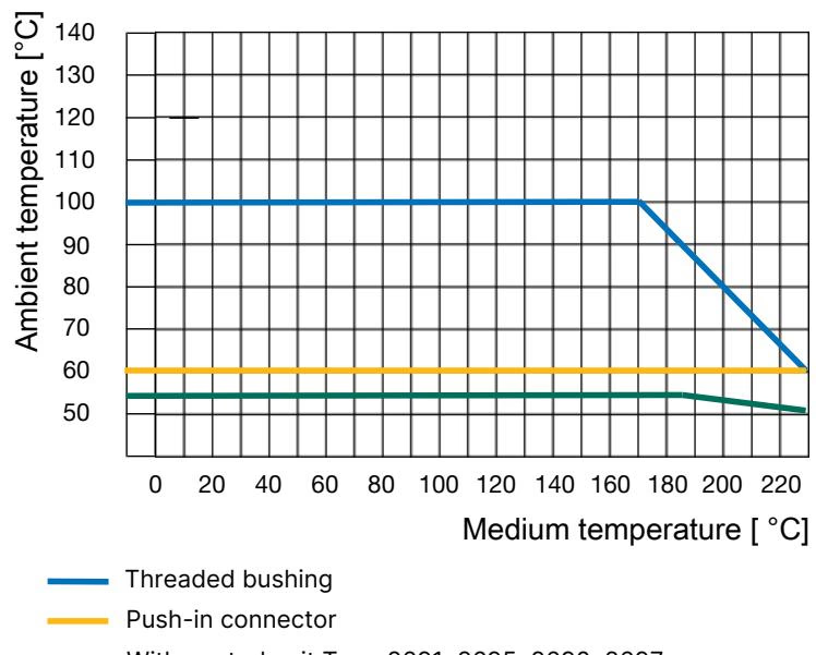
| Pilot Air Port Connection | Permissible Medium Temperature (PTFE Seal) | Permissible Ambient Temperature |
|---|---|---|
| Push-in connector (6 mm) | -10 °C to +230 °C | -10 °C to +60 °C |
| Threaded bushing (G 1/4) | -10 °C to +230 °C | -10 °C to +100 °C |
| Temperature | DIN EN 12516-1 / PN25 Pressure Rating | ASME B16.5 / B16.34 Cl. 150 Pressure Rating | JIS B 2220 10K Pressure Rating |
|---|---|---|---|
| -29 °C to +38 °C | - | 19.0 bar | - |
| -10 °C to +50 °C | 25.0 bar | 18.4 bar (at 50 °C) | 14.0 bar |
| 100 °C | 24.5 bar | 16.2 bar | 14.0 bar |
| 150 °C | 22.4 bar | 14.8 bar | 13.4 bar |
| 200 °C | 20.3 bar | 13.7 bar | 12.4 bar |
| 230 °C | 19.0 bar | 12.7 bar | 11.7 bar |
Application Limits
For article 20078458, the maximum continuous medium temperature is rated at +185 °C with a maximum rated operating pressure of 16 bar. The pressure must not exceed the ASME BPE clamp coupling limits or the derating curves specified in the table above.
The valve can be installed in any orientation, with the actuator pointing vertically upward being preferred. The flow arrow cast onto the CF3M valve body must match pipeline fluid flow.
When separating the pneumatic actuator from the CF3M valve body for maintenance or clamp installation, the valve must remain in the open position to prevent mechanical damage to the seat seal. Because control function B valves are held open by spring force, no pilot pressure is required during unthreading.
| Nominal Diameter (DN) | Actuator Size Code | Body Connection Tightening Torque | Tolerance |
|---|---|---|---|
| DN 15 | 40 (C), 50 (D), 63 (E) | 45 Nm | +10 / -5 Nm |
| DN 20 | 40 (C), 50 (D), 63 (E), 80 (F) | 50 Nm | +10 / -5 Nm |
| DN 25 | 50 (D), 63 (E), 80 (F) | 60 Nm | +10 / -5 Nm |
| DN 32 | 63 (E), 80 (F), 100 (G) | 65 Nm | +10 / -5 Nm |
| DN 40 | 63 (E), 80 (F), 100 (G), 125 (H) | 65 Nm | +10 / -5 Nm |
| DN 50 | 63 (E), 70 (M), 80 (F), 90 (N), 100 (G), 125 (H) | 70 Nm | +10 / -5 Nm |
| DN 65 | 80 (F), 100 (G), 125 (H) | 70 Nm | +10 / -5 Nm |
| DN 65 | 175 (K), 225 (L) | 100 Nm | +10 / -5 Nm |
| DN 80 | 125 (H), 130 (P) | 120 Nm | +10 / -5 Nm |
| DN 100 | 125 (H), 175 (K), 225 (L) | 150 Nm | +10 / -5 Nm |
Before re-screwing the actuator into the body, inspect the body seal ring and coat threads with food-grade lubricant paste (Klüber paste UH1 96-402).
The pilot air interface can be indexed 360° to accommodate pipe runs and control head cabling.
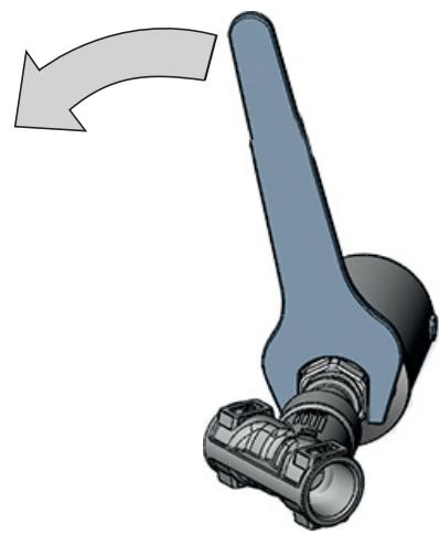
Rotational Direction Constraint
Rotate the actuator only in the specified direction. Turning the actuator in the opposite direction can loosen the body connection thread, causing media leakage.
Connect pilot air lines to pilot port 1 located on the actuator housing. The standard configuration uses 6 mm outer diameter pneumatic hoses inserted into the push-in connector.
Commissioning Sequence
To prevent uncontrolled movement during initial system pressurization or after plant shut-downs: first connect and pressurize the pneumatic pilot system (2.5 to 7.0 bar), and only then charge the piping system with fluid media.
Perform regular visual inspections during scheduled maintenance intervals to ensure external and internal tightness.
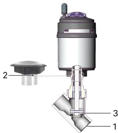
| Inspection Point | Observed Fault | Corrective Action |
|---|---|---|
| 1. Media connectors | Fluid leakage at ASME BPE clamp interface | Inspect gasket, check clamp tightening torque, align piping |
| 2. Relief bore | Fluid or pilot air leaking from actuator relief bore | Replace packing gland seal kit or complete actuator |
| 3. Swivel plate / seat | Internal bypass leakage across valve seat | Replace worn PTFE swivel plate assembly |
| Problem | Root Cause | Corrective Action |
|---|---|---|
| Actuator fails to switch | Pilot air port reversed | Connect pilot air supply exclusively to Port 1 for CFB |
| Actuator fails to switch | Insufficient pilot pressure | Increase pilot pressure to meet 2.5 to 7.0 bar specification |
| Actuator fails to switch | Line pressure exceeds limit | Verify pipeline operating pressure does not exceed 16 bar rating |
| Actuator fails to switch | Valve installed against flow | Align installation with body flow arrow (flow below seat) |
| Valve seat passes fluid (leaking) | Pilot pressure insufficient to hold closed | Increase pilot pressure to overcome seat counter-pressure |
| Valve seat passes fluid (leaking) | Particulates lodged on seat | Flush line; install upstream strainer (DIN EN 161) |
| Valve seat passes fluid (leaking) | PTFE swivel plate worn or deformed | Install a new Bürkert replacement swivel plate set |
| Leakage at actuator relief bore | Packing gland V-rings worn | Replace spindle packing gland using dedicated socket wrench |
Replacing the spindle packing gland requires the specialized deep socket wrench to avoid damaging guide bushings.
| Spindle Diameter | Valve Nominal Diameter (DN) | Width Across Flats (AF) | Article Number |
|---|---|---|---|
| 10 mm | DN 15 to DN 50 | 19 mm | 683221 |
| 14 mm | DN 32 to DN 80 | 21 mm | 683223 |
For DN65 (20078458), socket wrench article 683223 (AF 21 mm) is used.
Under supplemental standard code PX51, Type 2100 is approved as Category 2 non-electrical equipment for use in Zones 1/21 and 2/22 (EPS 18 ATEX 2 008 X / IECEx EPS 18.0007 X: Ex h IIC T4...T2 Gb / Ex h IIIC T135°C...T300°C Db).
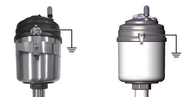
| Temperature Class | Maximum Permissible Surface Temperature | Ambient Temperature Range | Maximum Medium Temperature |
|---|---|---|---|
| T2 | 300 °C | -40 °C to +130 °C | 285 °C |
| T3 | 200 °C | -40 °C to +130 °C | 185 °C |
| T4 | 135 °C | -40 °C to +100 °C | 125 °C |
To prevent electrostatic discharge ignition hazards in classified areas:
Static Discharge Hazard
Accumulation of electrostatic charge on plastic actuator parts or insulated piping components presents an explosion hazard. The operator must ensure potential equalization across all conductive parts and prohibit dry wiping of the device in explosive gas or dust atmospheres.
Explore similar products in our catalog



