


PN25

BURKERT 20093362 (Type 2100) is a pneumatically operated 2/2-way angle seat valve with DN20 weld connections, normally closed (NC) operation, stainless steel body, PTFE seat seal, and 0-25 bar pressure rating.
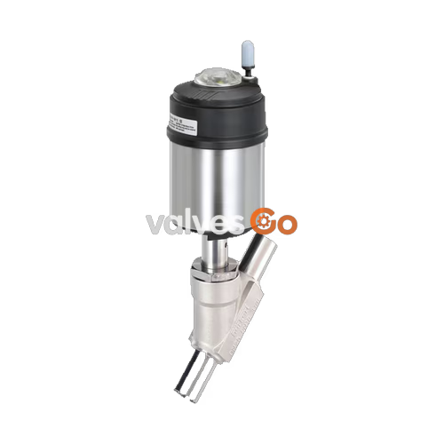
BURKERT 20093362 (Type 2100) is a pneumatically operated 2/2-way angle seat valve engineered for decentralized process automation in hygienic, steam, and aggressive fluid media. The assembly consists of a flow-optimized cast stainless steel CF3M valve body with welded pipe ends and an ELEMENT pneumatic piston actuator. Designed to meet DIN 11850 Series 2, DIN 11866 Series A, and DIN EN 10357 Series A standards at nominal size DN 20 (outer diameter 23.0 mm, wall thickness 1.5 mm), this unit provides a water flow factor Kv of 11 m³/h and an installation length of 115 mm. Operating under Control Function A (normally closed by internal spring force), the valve uses an under-seat flow configuration that prevents water hammer during liquid cycling and handles process pressures up to 25 bar(g).
Equipped with a 70 mm diameter (size M) pneumatic actuator, the valve requires a minimum pilot control pressure of 4.8 bar(g) and accommodates control pressures up to 10 bar(g). The wetted sealing configuration utilizes virgin PTFE for seat sealing and a self-adjusting PTFE V-ring packing gland with spring compensation, providing DIN EN 12266-1 Leakage Rate A bubble-tight shut-off. All wetted materials comply with European Regulation (EC) 1935/2004 for contact with food and beverage products. The valve is suitable for Clean-in-Place (CIP) and Steam-in-Place (SIP) routines at medium temperatures from -10 °C up to +140 °C.
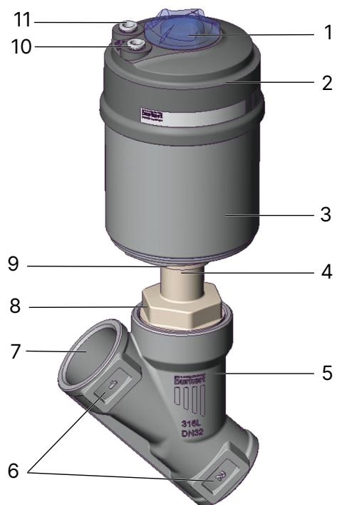
BURKERT 20093362 operates under Control Function A (normally closed, NC). In the unpressurized rest position, the actuator internal spring assembly pushes the spindle downward, seating the stainless steel swivel plate against the PTFE valve seat. Pressurizing pilot air port 1 lifts the piston and spindle assembly, allowing process media to flow through the seat.
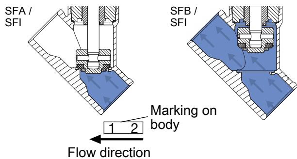
The flow path enters beneath the valve seat (flow to open). Because line pressure acts against the bottom of the swivel plate, line pressure assists opening stroke motion. This direction dampens closing impacts and prevents destructive pressure surges (water hammer) in incompressible liquid lines.
Operating Recommendations
Always maintain the flow path below the valve seat for liquid distribution. Directing liquid media above the seat can trigger severe water hammer during closure, resulting in pipeline shock and structural damage.
All components of the Type 2100 angle seat valve are constructed from corrosion-resistant alloys, high-performance thermoplastics, and fluoropolymer sealing materials.
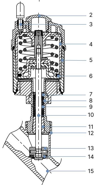
| Item | Component | Material |
|---|---|---|
| 1 | Ground terminal | Stainless steel 1.4301 / 1.4305 (supplied with ATEX variants) |
| 2 | Optical position indicator | Polysulfone (PSU) |
| 3 | Pilot air ports | Polypropylene (PP) push-in connector (G 1/8 stainless steel 1.4305 optional) |
| 4 | Actuator cover | Polyphenylene sulfide (PPS) |
| 5 | Actuator casing | Stainless steel 1.4561 (316Ti) |
| 6 | Piston seal | Fluoroelastomer (FKM) |
| 7 | Spring assembly | Stainless steel 1.4310 |
| 8 | Spindle pipe | Stainless steel 1.4401 (316) / 1.4404 (316L) |
| 9 | Packing gland | Filled PTFE V-rings with Belleville spring washer compensation |
| 10 | Valve spindle | Stainless steel 1.4401 (316) / 1.4404 (316L) |
| 11 | Spindle guide | Polyetheretherketone (PEEK) |
| 12 | Body seal | Graphite (PTFE optional) |
| 13 | Swivel plate | Stainless steel 1.4401 (316) / 1.4404 (316L) |
| 14 | Seat seal | PTFE (Polytetrafluoroethylene) |
| 15 | Valve body | Cast stainless steel CF3M (equivalent to AISI 316L) |
Lubricants utilized in the packing gland and internal actuator chamber are classified NSF H1 for incidental contact in food-processing environments.
Pressure ratings for BURKERT 20093362 comply with PN25 according to DIN EN 1333 and Class 150 according to DIN EN 1759. The maximum permissible operating pressure correlates directly with medium operating temperature in accordance with DIN EN 12516-1.
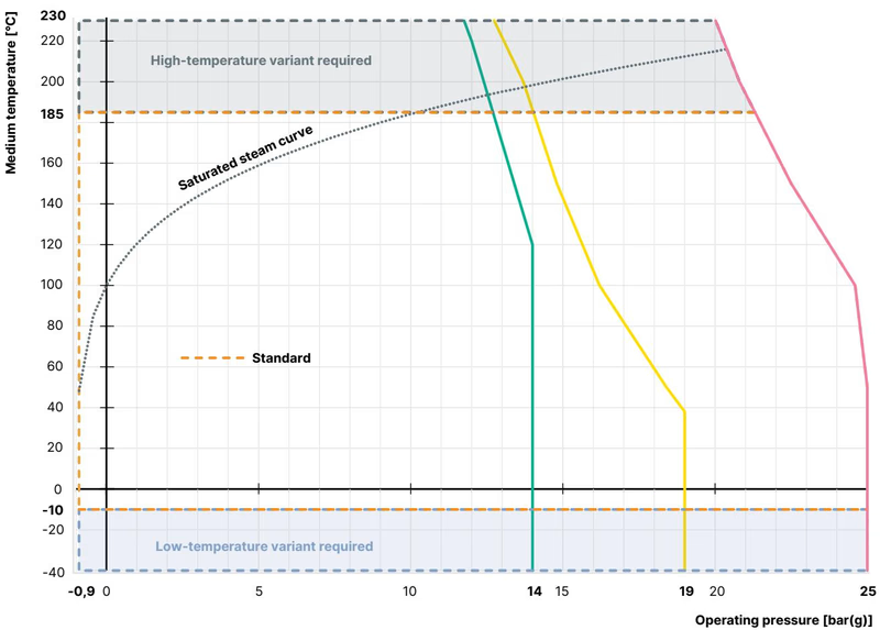
| Temperature [°C] | Maximum Permissible Operating Pressure [bar(g)] |
|---|---|
| -10 to +50 | 25.0 |
| +100 | 24.5 |
| +140 (Standard Limit) | 22.8 |
| +150 | 22.4 |
| +200 | 20.3 |
| +230 | 19.0 |
Below-seat fluidic performance values for Type 2100 welded variants operating with Control Function A and PTFE seat seals:
| Nominal Diameter (DN) | Seat Size (DN) | Actuator Size Ø [mm] | Flow Factor Kv (Water) [m³/h] | Min. Pilot Pressure [bar(g)] | Max. Operating Pressure [bar(g)] |
|---|---|---|---|---|---|
| DN 10 | 15 | 50 (D) | 2.5 | 5.2 | 25.0 |
| DN 10 | 15 | 70 (M) | 2.5 | 4.8 | 25.0 |
| DN 15 | 15 | 50 (D) | 5.3 | 5.2 | 25.0 |
| DN 15 | 15 | 70 (M) | 5.4 | 4.8 | 25.0 |
| DN 20 | 20 | 50 (D) | 10.0 | 5.2 | 16.0 |
| DN 20 (20093362) | 20 | 70 (M) | 11.0 | 4.8 | 25.0 |
| DN 25 | 25 | 50 (D) | 14.0 | 5.2 | 9.0 |
| DN 25 | 25 | 70 (M) | 18.0 | 4.8 | 16.0 |
| DN 25 | 25 | 90 (N) | 20.0 | 5.0 | 25.0 |
| DN 32 | 32 | 70 (M) | 26.0 | 4.8 | 8.5 |
| DN 32 | 32 | 90 (N) | 28.0 | 5.0 | 25.0 |
| DN 40 | 40 | 70 (M) | 35.0 | 4.8 | 6.0 |
| DN 40 | 40 | 90 (N) | 38.0 | 5.0 | 16.0 |
| DN 50 | 50 | 70 (M) | 49.0 | 4.8 | 4.0 |
| DN 50 | 50 | 90 (N) | 55.0 | 5.0 | 10.0 |
| DN 50 | 50 | 130 (P) | 60.0 | 5.0 | 25.0 (20.0) |
BURKERT 20093362 combines the 70 mm (M) actuator with a DN 20 welded body.
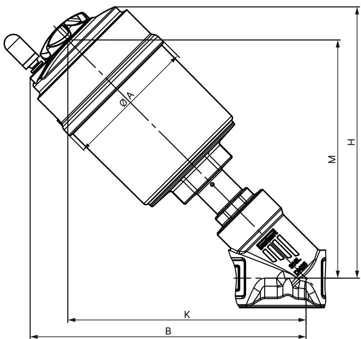
| Actuator Size | Ø A [mm] | B [mm] | H [mm] | K/M [mm] |
|---|---|---|---|---|
| 50 (D) | 64.5 | 174 | 171 | 155 |
| 70 (M) (20093362) | 91.0 | 189 | 186 | 163 |
| 90 (N) | 120.0 | 229 | 228 | 203 |
| 130 (P) | 159.0 | 293 | 293 | 254 |
Note: Dimensions B, H, K, and M are maximum figures and may vary by up to 6 mm based on connection type and orifice size.
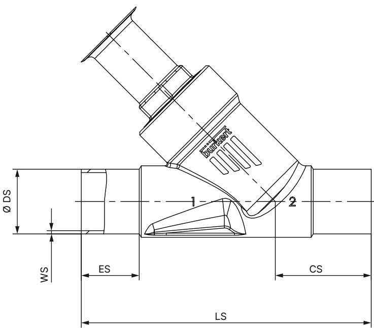
| DN | NPS | ES [mm] | CS [mm] | LS [mm] | Ø DS [mm] | WS [mm] |
|---|---|---|---|---|---|---|
| 10 | 3/8 | 30 | 46 | 135 | 13.0 | 1.5 |
| 15 | 1/2 | 19 | 34 | 100 | 19.0 | 1.5 |
| 20 (20093362) | 3/4 | 20 | 39 | 115 | 23.0 | 1.5 |
| 25 | 1 | 26 | 43 | 130 | 29.0 | 1.5 |
| 32 | 1 1/4 | 26 | 45 | 145 | 35.0 | 1.5 |
| 40 | 1 1/2 | 26 | 49 | 160 | 41.0 | 1.5 |
| 50 | 2 | 26 | 50 | 175 | 53.0 | 1.5 |
| 65 | 2 1/2 | 26 | 50 | 210 | 70.0 | 2.0 |
| 80 | 3 | 26 | 88.5 | 266 | 85.0 | 2.0 |
Hazard to Internal Seals During Welding
Do not weld the valve body into the pipeline with the actuator mounted. High welding temperatures conduct through the cast housing and will destroy the PTFE seat seal, body seal, and spindle packing.
| Nominal Diameter (DN) | Actuator Sizes | Tightening Torque [Nm] | Tolerance [Nm] |
|---|---|---|---|
| 15 | 40 (C), 50 (D), 63 (E) | 45 | +10 / -5 |
| 20 (20093362) | 40 (C), 50 (D), 63 (E), 70 (M) | 50 | +10 / -5 |
| 25 | 50 (D), 63 (E), 80 (F) | 60 | +10 / -5 |
| 32 | 63 (E), 80 (F), 100 (G) | 65 | +10 / -5 |
| 40 | 63 (E), 80 (F), 100 (G), 125 (H) | 65 | +10 / -5 |
| 50 | 63 (E), 70 (M), 80 (F), 90 (N), 100 (G), 125 (H) | 70 | +10 / -5 |
The pilot air connections can be rotated continuously through 360° to simplify pneumatic hose routing.
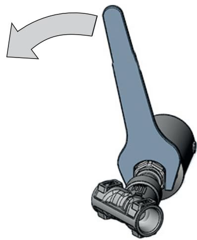
Direction of Rotation
Turn the actuator only in the clockwise direction indicated by the directional arrow. Turning counter-clockwise can loosen the threaded connection between body and actuator, resulting in media leakage.
BURKERT 20093362 features integrated pilot air ports designated 1 and 2 on the actuator head. For Control Function A, pilot control pressure connects exclusively to port 1.
Regular inspections must confirm external tightness and absence of media seepage at the relief bore. Media discharge from the relief bore indicates wear of the PTFE spindle packing gland.
| Symptom | Probable Cause | Corrective Action |
|---|---|---|
| Actuator fails to stroke | Pilot pressure interchanged or below 4.8 bar | Verify pilot line is attached to port 1; confirm pilot pressure reaches 4.8 to 10 bar |
| Actuator fails to stroke | Operating line pressure exceeds 25 bar | Verify process pressure matches technical rating on type label |
| Valve seat fails to seal | Foreign particulate wedged on seat | Flush pipeline; install an upstream particulate strainer |
| Valve seat fails to seal | PTFE swivel seal worn or scored | Replace the swivel plate and seat assembly using original spare kit |
| Fluid leaks from relief bore | Packing gland V-rings worn | Replace the PTFE packing gland assembly using socket wrench tool 683221 |
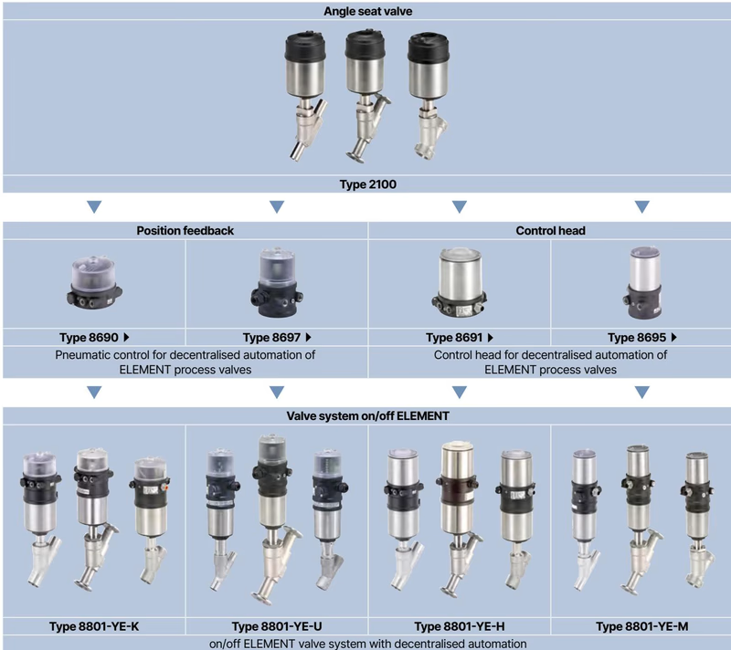
The ELEMENT housing interface allows modular attachment of decentralized control tops and feedback heads without external piping.
Explore similar products in our catalog



