


PN25

BURKERT 20093947 Type 2100 is a pneumatic 2/2-way angle seat valve featuring ASME BPE DN20 weld ends, normally closed control function A, PTFE seat seal, and 0 to 16 bar operating pressure.
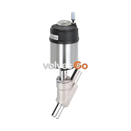
BURKERT 20093947 (Type 2100) is a pneumatically operated 2/2-way angle seat valve designed for decentralized process automation in sanitary, chemical, and hygienic process lines. Featuring a flow-optimized cast stainless steel CF3M body, this variant is manufactured with ASME BPE / DIN 11866 Series C weld ends in nominal size DN 20 (3/4"). Operating under Control Function A (normally closed by spring force), the valve uses a 50 mm (size D) pneumatic piston actuator that routes flow under the valve seat, eliminating water hammer when handling liquid media while maintaining tight shut-off on clean steam, gases, and corrosive process fluids.
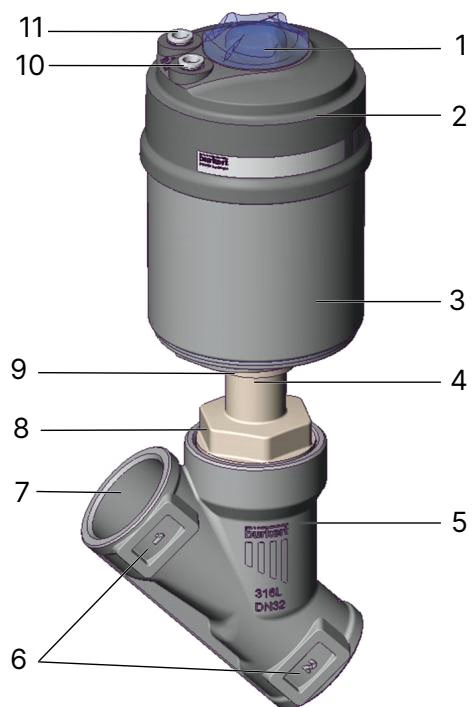
| Item | Description | Item | Description |
|---|---|---|---|
| 1 | Transparent cap with position indicator | 7 | Port connection (ASME BPE weld end) |
| 2 | Actuator cover (PPS) | 8 | Body connection nut |
| 3 | Actuator housing (Stainless steel 1.4561) | 9 | Actuator connection |
| 4 | Relief bore (spindle gland leak indicator) | 10 | Pilot air port 1 |
| 5 | Valve body (Stainless steel CF3M) | 11 | Pilot air port 2 (exhaust/vent) |
| 6 | Flow direction arrow marking |
Burkert 20093947 operates using Control Function A (CFA). In its de-energized rest state, mechanical spring force pushes the actuator piston downward, seating the PTFE seal plate tightly against the orifice to close the valve. When pilot air of at least 5.2 bar(g) enters pilot air port 1, it overcomes the spring force, retracting the spindle and lifting the swivel plate into the full open position.
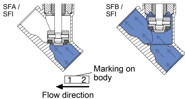
The flow path is configured below the seat (flow-to-open). Because process pressure acts on the underside of the swivel plate, line pressure assists in opening the valve. This flow configuration is required for liquid applications to prevent rapid deceleration and pressure surges (water hammer). It is fully qualified for liquid media, saturated steam, and technical gases.
Flow and Pressure Parameters
Wetted surfaces are constructed from austenitic stainless steel and fluoropolymer compounds certified to Regulation (EC) 1935/2004 for food contact and compatibility with Clean-in-Place (CIP) and Sterilize-in-Place (SIP) thermal regimes. Spindle sealing is achieved using self-adjusting PTFE V-rings preloaded with packing springs and lubricated with NSF H1 compliant grease.
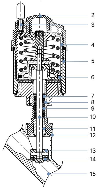
| Item | Component | Standard Material Specification |
|---|---|---|
| 1 | Ground terminal | Stainless steel 1.4301 / 1.4305 (included on ATEX-certified variants) |
| 2 | Optical position indicator | Polysulfone (PSU) |
| 3 | Pilot air port | Polypropylene (PP) push-in connector (G 1/8" stainless steel 1.4305 on request) |
| 4 | Actuator cover | Polyphenylene sulphide (PPS) |
| 5 | Actuator casing | Stainless steel 1.4561 (316Ti) |
| 6 | Piston seal | Fluorocarbon elastomer (FKM) |
| 7 | Actuator spring | Stainless spring steel 1.4310 |
| 8 | Tube / Actuator neck | Stainless steel 1.4401 (316) / 1.4404 (316L) |
| 9 | Spindle packing gland | PTFE V-rings (carbon-filled), spring-compensated |
| 10 | Valve spindle | Stainless steel 1.4401 (316) / 1.4404 (316L) |
| 11 | Spindle guide | Polyetheretherketone (PEEK) |
| 12 | Body seal | Graphite (PTFE optional) |
| 13 | Swivel plate | Stainless steel 1.4401 (316) / 1.4404 (316L) |
| 14 | Seat seal | PTFE (Polytetrafluoroethylene) |
| 15 | Valve body | Cast stainless steel CF3M (equivalent to AISI 316L) |
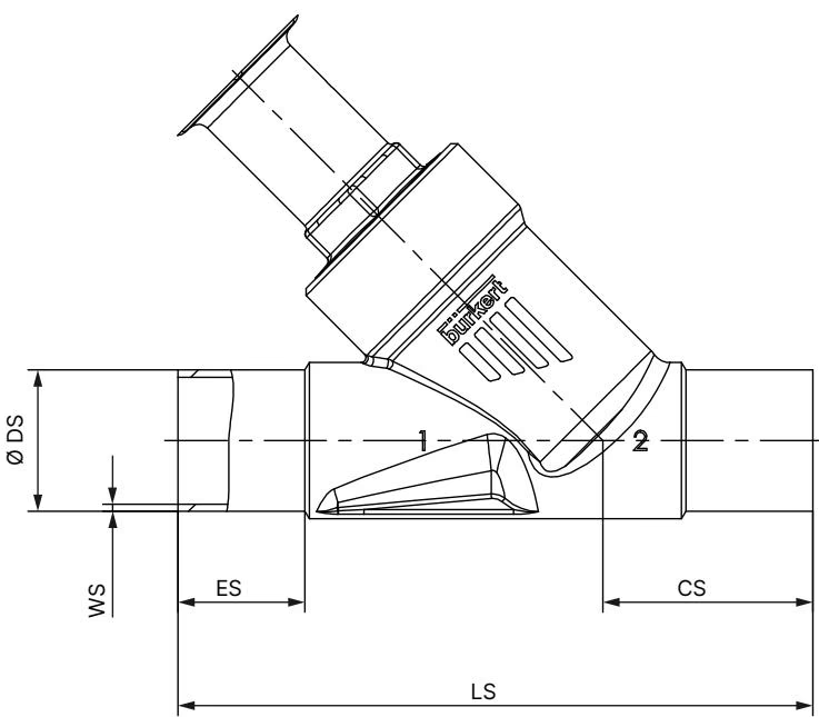
| Size (NPS) | Size (DN) | Insertion Depth ES [mm] | Port Height CS [mm] | Length LS [mm] | Outer Diameter ∅ DS [mm] | Wall Thickness WS [mm] |
|---|---|---|---|---|---|---|
| 1/2" | DN 15 | 30 | 46 | 135 | 12.70 | 1.65 |
| 3/4" | DN 20 (20093947) | 30 | 52 | 145 | 19.05 | 1.65 |
| 1" | DN 25 | 30 | 51 | 152 | 25.40 | 1.65 |
| 1 1/2" | DN 40 | 30 | 60 | 182 | 38.10 | 1.65 |
| 2" | DN 50 | 30 | 64 | 210 | 50.80 | 1.65 |
| 2 1/2" | DN 65 | 26 | 56 | 230 | 63.50 | 1.65 |
| 3" | DN 80 | 26 | 88.5 | 266 | 76.20 | 1.65 |
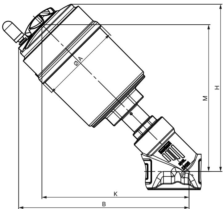
| Actuator Size | Actuator ∅ A [mm] | Base Actuator B [mm] | Base Actuator H [mm] | Centerline Clearance K/M [mm] | Height with Type 8690 / 8697 [mm] | Height with Type 8691 / 8695 [mm] |
|---|---|---|---|---|---|---|
| 50 (D) – DN 20 | 64.5 | 174 | 171 | 155 | 234 | 247 |
| 70 (M) – DN 20 | 91.0 | 189 | 186 | 163 | 240 | 264 |
Note: Dimensions B, H, K, and M are maximum values and can decrease by up to 6 mm depending on weld pipe tolerances.
The operating boundary of Burkert 20093947 is determined jointly by the mechanical rating of the CF3M valve body and the thermal limits of the pneumatic pilot connections.
| Temperature [°C] | Class 150 Limit [bar(g)] | PN 25 Limit [bar(g)] | Article 20093947 Operating Limit [bar(g)] |
|---|---|---|---|
| -29 to +38 | 19.0 | 25.0 | 16.0 |
| +50 | 18.4 | 25.0 | 16.0 |
| +100 | 16.2 | 24.5 | 16.0 |
| +150 | 14.8 | 22.4 | 14.8 |
| +185 | 13.9 | 20.9 | 13.9 |
| +200 | 13.7 | 20.3 | Not permitted (variant limit +185 °C) |
Welded Connection Notice
Never weld a valve body into a pipeline while the actuator mechanism is attached. Radiant and conductive welding heat will destroy the internal PTFE seat seal, spindle packing rings, and FKM actuator seals.
| Nominal Valve Size | Actuator Size | Tightening Torque [Nm] | Tolerance [Nm] |
|---|---|---|---|
| DN 15 | 40 (C), 50 (D), 63 (E) | 45 | +10 / -5 |
| DN 20 (20093947) | 50 (D), 70 (M) | 50 | +10 / -5 |
| DN 25 | 50 (D), 63 (E), 80 (F) | 60 | +10 / -5 |
| DN 32 | 63 (E), 80 (F), 100 (G) | 65 | +10 / -5 |
| DN 40 | 63 (E), 80 (F), 100 (G), 125 (H) | 65 | +10 / -5 |
| DN 50 | 70 (M), 90 (N), 130 (P) | 70 | +10 / -5 |
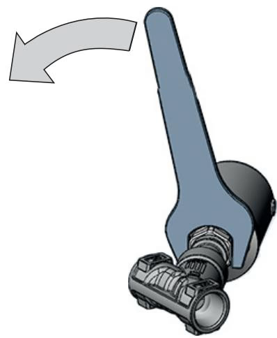
The actuator assembly rotates 360° continuously to facilitate clean routing of pneumatic hoses and electrical cabling.
Actuator Rotation Precaution
Pressurize pilot air port 1 with 5 bar compressed air to open the valve before turning the actuator. Hold the body connection hexagon with a fixed counter-wrench and turn the actuator hex nut only in the direction indicated in the figure. Turning in the reverse direction loosens the body connection and causes process fluid leakage.
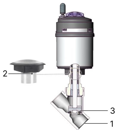
| Inspection Point | Observed Fault | Corrective Action |
|---|---|---|
| Port connections (1) | External pipe joint leakage | Re-weld joint or replace flange/clamp gaskets |
| Relief bore (2) | Fluid leaking from actuator neck bore | Packing gland worn; replace packing set or replace actuator assembly |
| Valve seat (3) | Internal bypass / seat leakage | Swivel plate worn or contaminated; clean seat or install new swivel plate |
| Symptom | Probable Cause | Remedial Action |
|---|---|---|
| Actuator does not stroke | Supply line connected to wrong port | Connect control pressure directly to pilot air port 1 |
| Pilot pressure below 5.2 bar(g) | Increase pilot supply pressure to 5.2–10 bar(g) range | |
| Operating line pressure exceeds 16 bar(g) | Verify process pressure complies with valve rating | |
| Valve seat bypass leakage | Particulate matter lodged in orifice | Dismantle actuator and flush pipeline / clean seating surface |
| Worn or scored PTFE seat seal | Replace swivel plate assembly using spare kit | |
| Fluid flow inverted | Check flow arrow on body; ensure medium enters under the seat | |
| Continuous leak at relief bore | Spindle packing V-rings worn | Replace packing gland using installation tool (AF 19 mm, article 683221) |
Replacement of the internal spindle packing gland requires the dedicated Bürkert packing gland socket wrench. For DN 20 valves with a 10 mm spindle diameter, use socket wrench AF 19 mm (Bürkert Article No. 683221).
Explore similar products in our catalog



