PN25

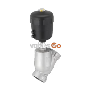
BURKERT Type 2961 (Model 20099319) manually operated 2-way globe control valve. Features DN 50 flange connection, stainless steel body, and PTFE seal for up to 25 bar.
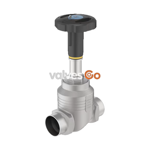
BURKERT Type 2961 (Model 20099319) is a manually operated 2-way globe control valve designed for excellent control accuracy. It consists of a manual actuator and a globe valve body with exchangeable seats made of high-quality stainless steel. The precise spindle guide enables control even under demanding operating conditions. A soft PTFE seal guarantees reliable sealing. The actuator is made of high-quality plastic and is suitable for use in demanding environments. It possesses a visual position indicator and can be optionally equipped with stroke limitation and locking.

Explosion Risk in Ex Areas
For variants with Ex approval, there is a risk of explosion due to electrostatic charging. Take appropriate measures to ensure that no electrostatic charge can build up in the potentially explosive area. Only wipe the device surfaces gently with a damp or antistatic cloth. Ground the actuator and valve body.
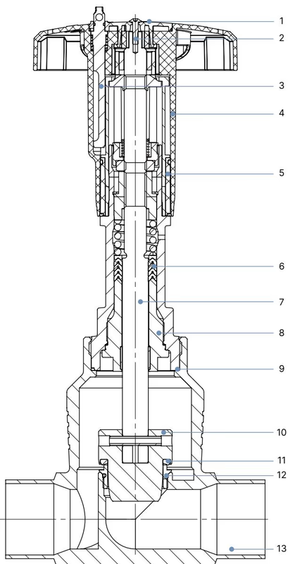
| No. | Element | Material |
|---|---|---|
| 1 | Cover | Polyamide (PA) |
| 2 | Screw | Stainless steel 1.4301 |
| 3 | Locking device | Stainless steel 1.4305 |
| 4 | Handwheel | Polyphenylene sulphide (PPS) |
| 5 | Visual position indicator with scale | Polyamide (PA) |
| 6 | Packing gland | PTFE V-rings (filled), with spring compensation |
| 7 | Stem | Stainless steel 1.4401 or 1.4404 |
| 8 | Spindle guide | Stainless steel 1.4404 (316L), PTFE filled |
| 9 | Housing seal | Graphite |
| 10 | Control cone | 1.4571 (optionally hardened) |
| 11 | Seat seal (optional) | PTFE or PEEK |
| 12 | Valve seat with O-ring | Stainless steel 1.4571, EPDM |
| 13 | Valve body | Stainless steel 316L/CF3M |
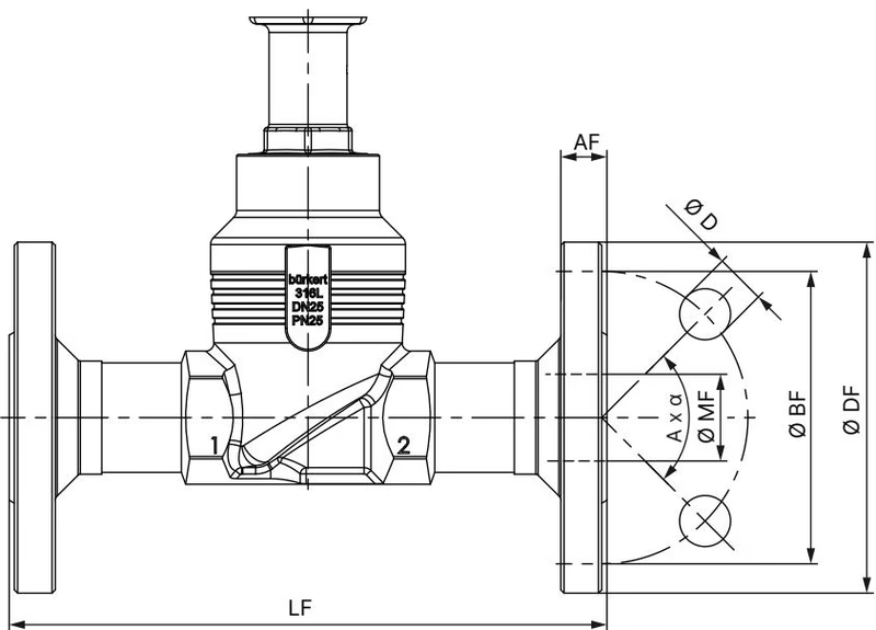
Dimensions in mm, unless otherwise stated. Nominal diameter DIN EN 1092-1 PN 25 FTF 1 according to DIN EN 558-1.
| DN | ∅ DF | LF | ∅ BF | AF | ∅ D | A x α | ∅ MF |
|---|---|---|---|---|---|---|---|
| 15 | 95 | 130 | 65 | 16 | 14 | 4 × 90° | 18.1 |
| 20 | 105 | 150 | 75 | 18 | 14 | 4 × 90° | 23.7 |
| 25 | 115 | 160 | 85 | 18 | 14 | 4 × 90° | 29.7 |
| 32 | 140 | 180 | 100 | 18 | 18 | 4 × 90° | 38.4 |
| 40 | 150 | 200 | 110 | 18 | 18 | 4 × 90° | 44.3 |
| 50 | 165 | 230 | 125 | 20 | 18 | 4 × 90° | 56.3 |
| 65 | 185 | 290 | 145 | 22 | 18 | 8 × 45° | 66.0 |
| 80 | 200 | 310 | 160 | 24 | 18 | 8 × 45° | 81.0 |
| 100 | 235 | 350 | 190 | 24 | 22 | 8 × 45° | 100.0 |
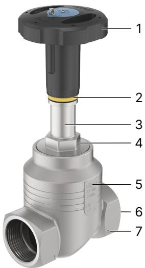
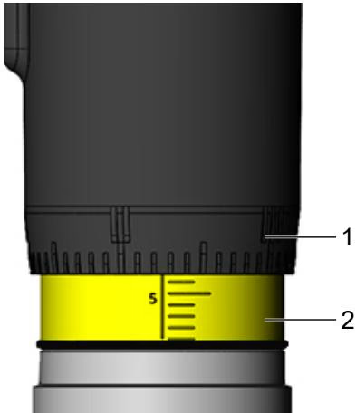
When turning the handwheel anticlockwise, the reproducible stroke scale becomes visible between the position indicator and the handwheel. The scale on the handwheel determines the rotation position of the handwheel (50 positions). The reproducible stroke scale shows, depending on the bottom edge of the handwheel, the relative position of the valve (valve opening) and acts as a fixation point for determining the rotation position.
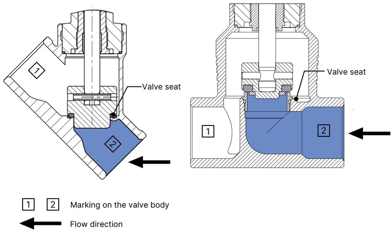
The valve seat is always closed against the medium flow. The flow direction should therefore be set such that the valve reaches the flow beneath the valve seat.
Risk of injury due to high pressure
Switch off the pressure before working on the device or system. Vent or drain the lines.
Setting the minimum and maximum stroke limit is possible as an option. An adjusting sleeve is used for this purpose.
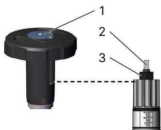
It is also an option to lock the handwheel to prevent unintentional or unauthorised operation of the valve. Handwheel sizes M and L can be locked in 13 locking positions per revolution.
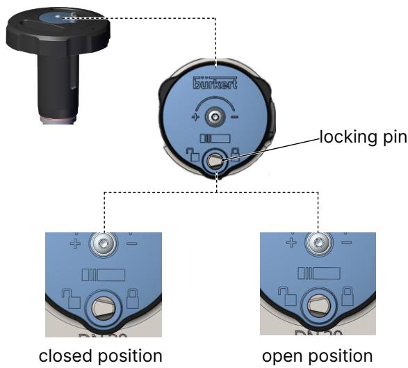
The locking pin has a bore (Ø 3.8) and can be secured against unauthorised use with a padlock (not included in scope of delivery). Push the locking pin down and rotate by 180°. Insert padlock through the bore in the locking pin and secure.
When used in accordance with the operating instructions, the actuator of the manually operated valve is maintenance-free. Perform a visual inspection of the device once per year. If leaks occur, replace the respective wearing part. Muddy and abrasive media require correspondingly shorter inspection intervals.
Explore similar products in our catalog