


PN25

Yoshitake GP-1000TSS pilot-operated pressure reducing valve for air and non-corrosive gases. Features stainless steel wetted parts, 0.1-1.0 MPa inlet pressure, and zero leakage.
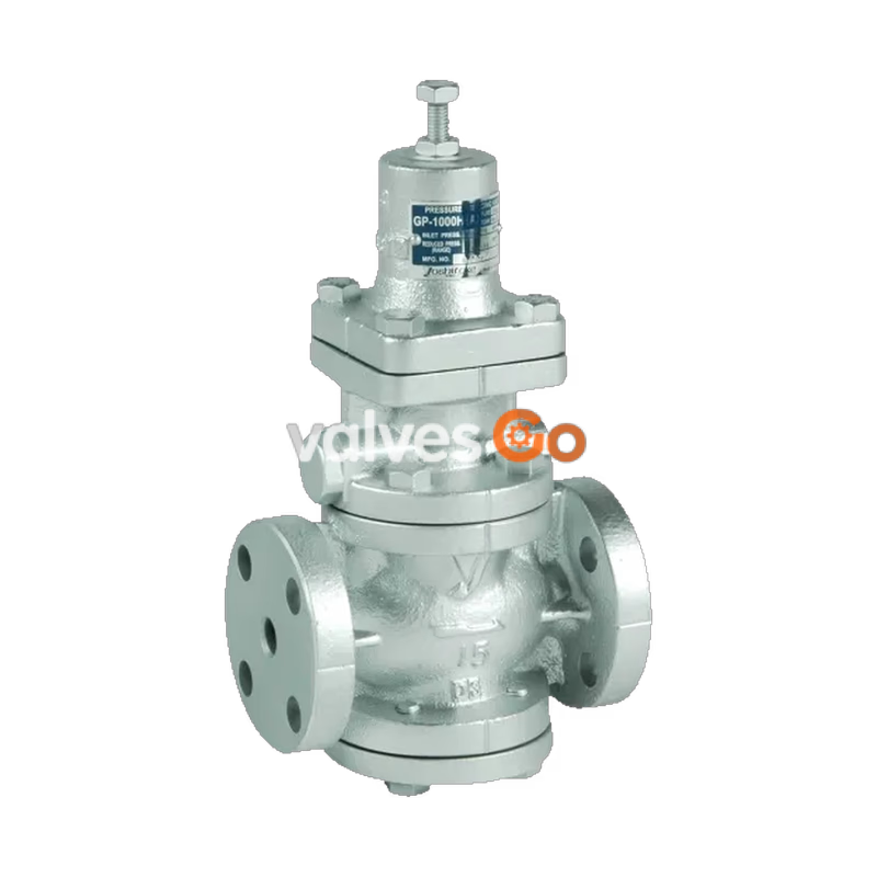
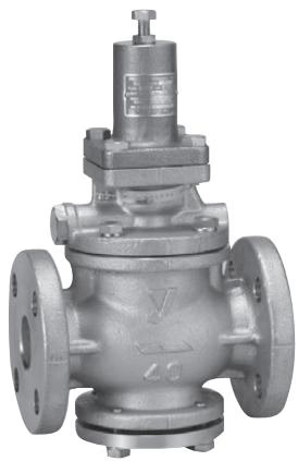
Yoshitake GP-1000TSS and GP-1000TAS are pilot-operated pressure reducing valves designed for air and non-corrosive gases. The GP-1000TSS features stainless steel wetted parts, while the GP-1000TAS is constructed entirely of stainless steel for maximum corrosion resistance. They offer a stable reduced pressure with an inlet pressure range of 0.1 to 1.0 MPa and zero valve seat leakage.
| Item | Description |
|---|---|
| Application | Air, Other non-dangerous fluids |
| Inlet pressure | 0.1-1.0 MPa |
| Reduced pressure | 0.05-0.9 MPa |
| Adjusted reduced pressure | 90% or less of inlet pressure (gauge pressure) |
| Minimum differential pressure | 0.05 MPa |
| Maximum pressure reduction ratio | 20:1 |
| Application temperature | 5-80°C |
| Valve seat leakage | None |
| Connection | JIS 10K FF flanged |
Material
| Part | Material |
|---|---|
| Body | Cast stainless steel |
| Valve | Stainless steel (NBR contained) |
| Valve seat | Stainless steel |
| Piston, cylinder | Stainless steel |
| Diaphragm | Stainless steel |
WARNING
Use on a compressed air system with air from oil-free compressors may cause deterioration of rubber parts in a short time (ozone crack). Please consult with us before such installation.
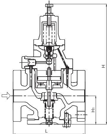
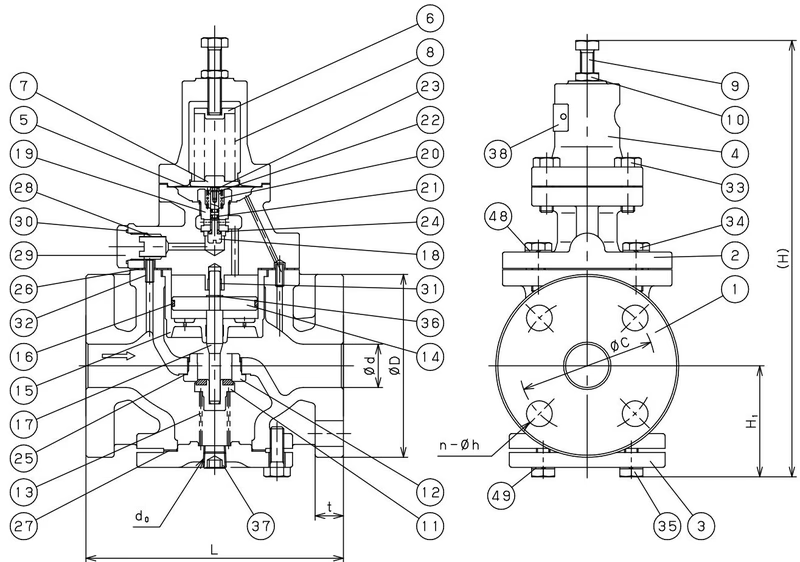
| Nominal size | L | H1 | H | Weight |
|---|---|---|---|---|
| 15A | 150 | 67 | 288 (298) | 8.3 (8.5) |
| 20A | 155 | 67 | 288 (298) | 8.8 (9.0) |
| 25A | 160 | 70 | 303 (313) | 10.5 (10.7) |
| 32A | 190 | 85 | 326 (336) | 14.8 (15.0) |
| 40A | 190 | 85 | 326 (336) | 15.3 (15.5) |
| 50A | 220 | 96 | 350 (360) | 20.8 (21.0) |
The above values in parentheses are the dimensions and weights of the GP-1000TAS.
Loading Air Pressure-set Pressure Chart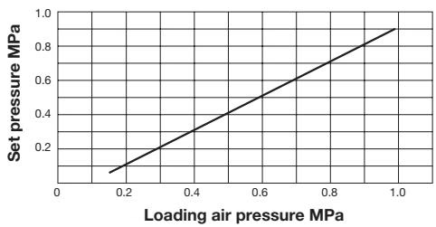
Specifications Selection Chart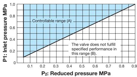 Find the intersection point of the inlet and reduced pressures. If the intersection point is within range (A), the pressures are controllable. The valve does not fulfill specified performance if the intersection point lies in range (B).
Table of Corrected Cv Values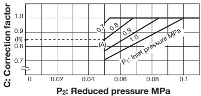 If the inlet pressure exceeds 0.7 MPa, and the pressure reducing ratio exceeds 10:1, find the appropriate correction coefficient C using chart above, and multiply the rated Cv value, and obtain the corrected Cv value.
Flow Characteristic Chart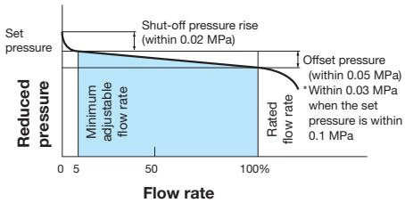
Pressure Characteristic Chart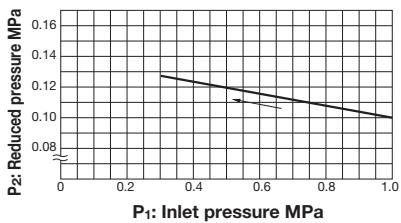 This chart shows variation in reduced pressure when the inlet pressure of 1.0 MPa is changed between 0.3 MPa and 1.0 MPa while the reduced pressure is set at 0.1 MPa.
Nominal Sizes Selection Chart (Fluid: 20°C Air)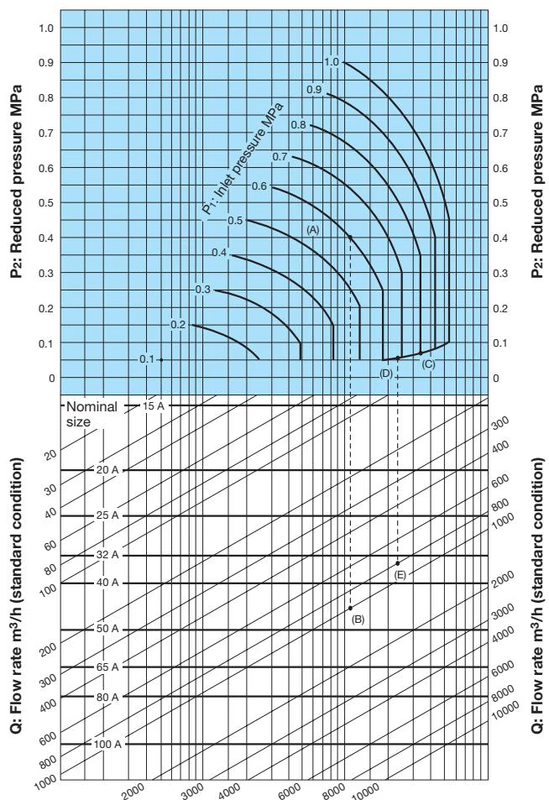
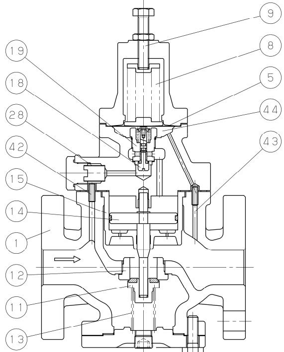
| No. | Parts name |
|---|---|
| 1 | Body |
| 5 | Diaphragm |
| 8 | Adjusting spring |
| 9 | Adjusting screw |
| 11 | Main valve |
| 12 | Main valve seat |
| 14 | Piston |
| 15 | Cylinder |
| 18 | Pilot valve |
| 19 | Pilot valve seat |
| 28 | Strainer |
| 42 | Inlet press. passage |
| 43 | Reduced press. Sensing port |
| 44 | Diaphragm chamber |
The pressure reducing valve reduces pressure by the throttling the valve. The valve is composed of the main valve and main valve seat for throttling, and adjusting spring, diaphragm, pilot valve, and piston for pressure sensing and activation.
Yoshitake Control Valves / Pressure Reducing Valves
GP, GD, and CP series for stable pressure reduction and control in steam, water, and air systems.
Explore similar products in our catalog



