ENP Nickel Plating

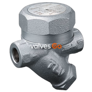
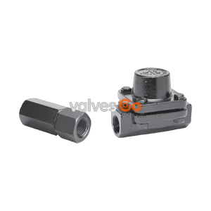
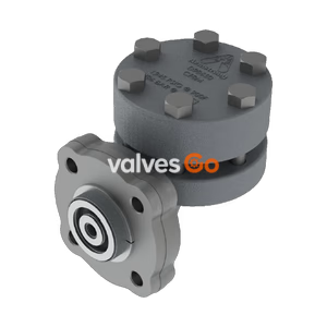
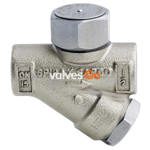
TLV P65SRN thermodynamic steam trap with thermostatic air vent. Used without adjustment for medium capacity applications up to 6.5 MPaG. Minimum operating pressure 0.03 MPaG.
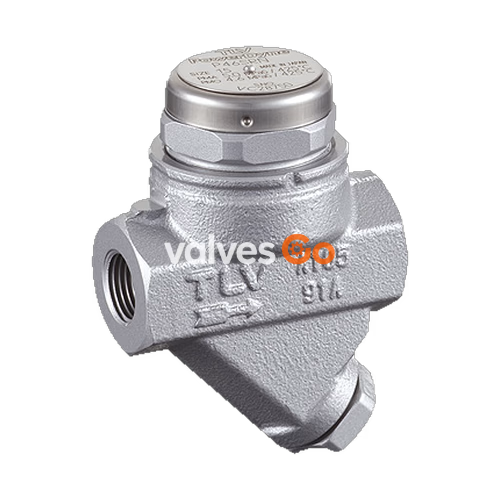
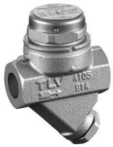
TLV P65SRN inline repairable thermodynamic steam trap with thermostatic air vent. It can be used without adjustment for medium capacity applications between 0.03 and 4.6 or 6.5 MPaG (5 and 650 or 925 psig), such as steam mains, tracers, and coils. The trap discharges condensate at a temperature slightly lower than saturation temperature.
WARNING
Install properly and DO NOT use this product outside the recommended operating pressure, temperature and other specification ranges.
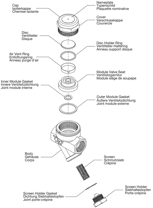
| No. | Description | M* | R* | No. | Description | M* | R* |
|---|---|---|---|---|---|---|---|
| 1 | Body | 8 | Nameplate | √ | |||
| 2 | Module Valve Seat | √ | 9 | Inner Module Gasket | √ | √ | |
| 3 | Cover | √ | 10 | Screen | √ | ||
| 4 | Disc | √ | 11 | Screen Holder Gasket | √ | √ | |
| 5 | Disc Holder Ring | √ | 12 | Screen Holder | |||
| 6 | Air Vent Ring (Bimetal) | √ | 13 | Cap | √ | ||
| 7 | Outer Module Gasket | √ | √ | 14 | Flange |
*M = Maintenance Kit; R = Repair Kit; replacement parts are available only in their respective kits.
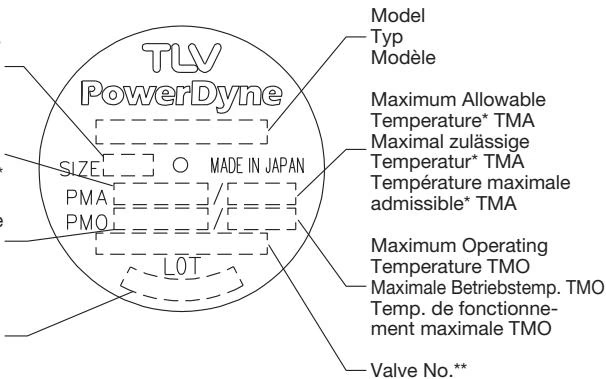
Refer to the product nameplate for detailed specifications.
Check to make sure that the pipes connected to the trap have been installed properly.
| Requirement | Correct | Incorrect |
|---|---|---|
| Install a catchpot of the proper diameter. | - | Diameter is too small. |
| Make sure the flow of condensate is not obstructed. | - | Diameter is too small and inlet protrudes into pipe. |
| To prevent rust and scale from flowing into the trap, connect the inlet pipe 25 – 50 mm (1 - 2 in) above the base of the T-pipe. | - | Rust and scale flow into the trap with the condensate. |
| When installing on the blind end, make sure nothing obstructs the flow of condensate. | - | Condensate collects in the pipe. |
| Status | Description |
|---|---|
| Normal | Condensate is discharged in a short blast followed by a longer period of no drainage. During the discharge, flash steam may be seen. A small amount of flash steam may be visible after the discharge. |
| Blocked | No condensate is discharged. The trap is quiet and makes no noise. The surface temperature of the trap is low. |
| Blowing | Live steam continually flows from the outlet, and there is a continuous metallic sound. |
| Steam Leakage | Live steam is discharged through the trap outlet together with condensate, accompanied by a high-pitched sound. |
| Chattering | The trap does not close properly. Steam is discharged from the trap in short rapid bursts. |
Operational inspections should be performed at least twice per year, or as called for by trap operating conditions. Steam trap failure may result in temperature drop in the equipment, poor product quality or losses due to steam leakage.
Parts Inspection Procedure
| Problem | Cause | Remedy |
|---|---|---|
| No condensate is discharged (blocked) or discharge is poor | Screen is clogged with rust or scale | Clean |
| Air vent ring (bimetal) is broken or worn, causing air-binding | Replace air vent ring | |
| Disc holder ring is broken or worn, causing air-binding | Replace disc holder ring | |
| Disc is sticking to valve seat (due to oil, etc.) | Clean | |
| Steam-locking has occurred | Perform a bypass blow-down, or close the trap inlet valve and allow the trap to cool. Piping correction may also be required. | |
| Trap capacity is insufficient | Change to trap of suitable capacity | |
| Differential pressure is low | Study inlet/outlet pressure, including rise in outlet pipe | |
| Steam leakage or blowing (from valve seat) | Valve closure is obstructed by scale, etc. | Clean or replace screen |
| Disc or valve seat is worn | Replace worn parts | |
| Air vent ring (bimetal) or disc holder ring is broken, obstructing valve closure | Replace air vent ring or disc holder ring | |
| Back pressure exceeds allowable value | Use within pressure range | |
| Trap is being used below minimum operating pressure | Use within pressure range | |
| Disc is sticking to top of cover (due to oil, etc.) | Clean | |
| Valve chattering (Leakage) | Foreign matter or oil film on disc or valve seat | Clean |
| Scratches on disc or valve seat | Replace disc or valve seat | |
| Disc or valve seat is worn | Replace disc or valve seat | |
| Leakage from a location other than valve seat | Bypass valve is damaged or open | Replace or close bypass valve |
| Cover is loose or module gaskets are damaged | Tighten cover or replace module gaskets | |
| Cover is loose or sealing surface between cover and valve seat is damaged | Tighten or replace cover, or replace valve seat |
The BD2 Blowdown Valve, installed in place of the screen holder, uses internal pressure to blow out condensate/steam, dirt and scale to the atmosphere.

WARNING
When operating the blowdown valve, stand to the side well clear of the outlet to avoid contact with internal fluids that will be discharged. Operate the valve slowly and surely.
Reassembly of Blowdown Valve

Explore similar products in our catalog